Polymeric Stent

a polymer stent and stent technology, applied in the direction of prosthesis, buttons, blood vessels, etc., can solve the problems of strut cracking or fracture during crimping, relatively high recoil of polymer stents, and potentially low radial strength

Active Publication Date: 2010-01-07
ABBOTT CARDIOVASCULAR
View PDF16 Cites 286 Cited by
  • Summary
  • Abstract
  • Description
  • Claims
  • Application Information

AI Technical Summary

Benefits of technology

[0020]In further aspects, one of the linear link struts within the end segment is a marker strut that includes one or more holes. In detailed aspects, a closed cell immediately adjacent to one side of the marker strut is a mirror image or is substantially a mirror image of a closed cell immediately adjacent to the opposite side of the marker strut. In other detailed aspects, a first cell from among the closed cells of the end segment includes a first c

Problems solved by technology

Problems with PTCA include formation of intimal flaps or torn arterial linings, both of which can create another occlusion in the lumen of the coronary artery.
Moreover, thrombosis and restenosis may occur several months after the procedure and create a need for additional angioplasty or a surgical bypass operation.
Relatively low radial strength potentially contributes to relatively high recoil of polymer stents after implantation into an anatomical lumen.
Another potential problem with polymer stents is that struts can cra

Method used


Image

  • Polymeric Stent
  • Polymeric Stent
  • Polymeric Stent

Examples


Embodiment Construction

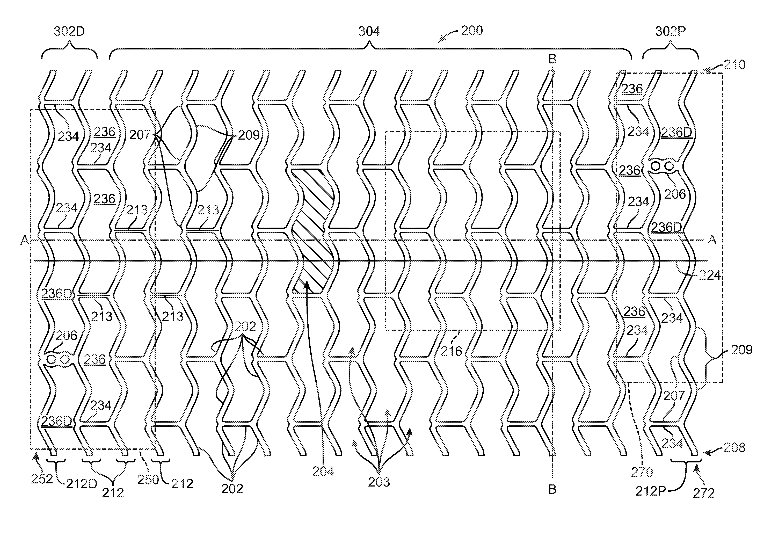
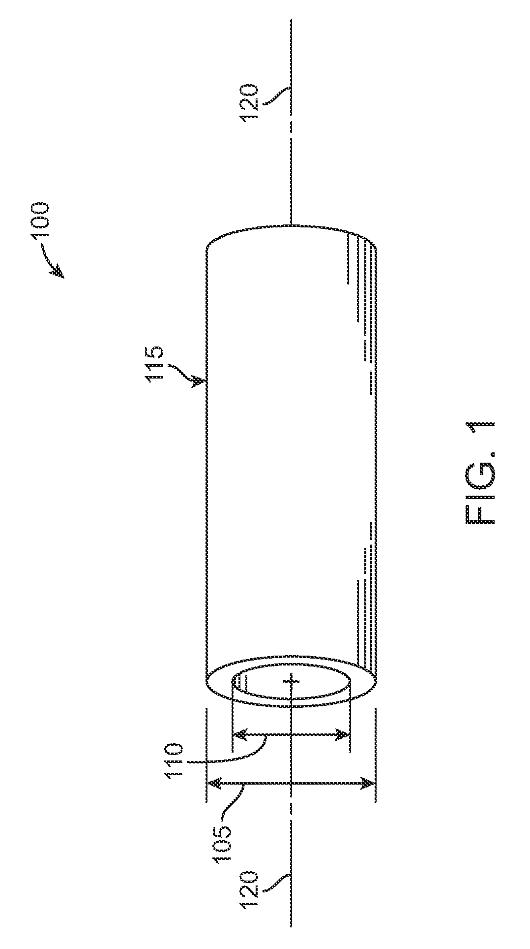
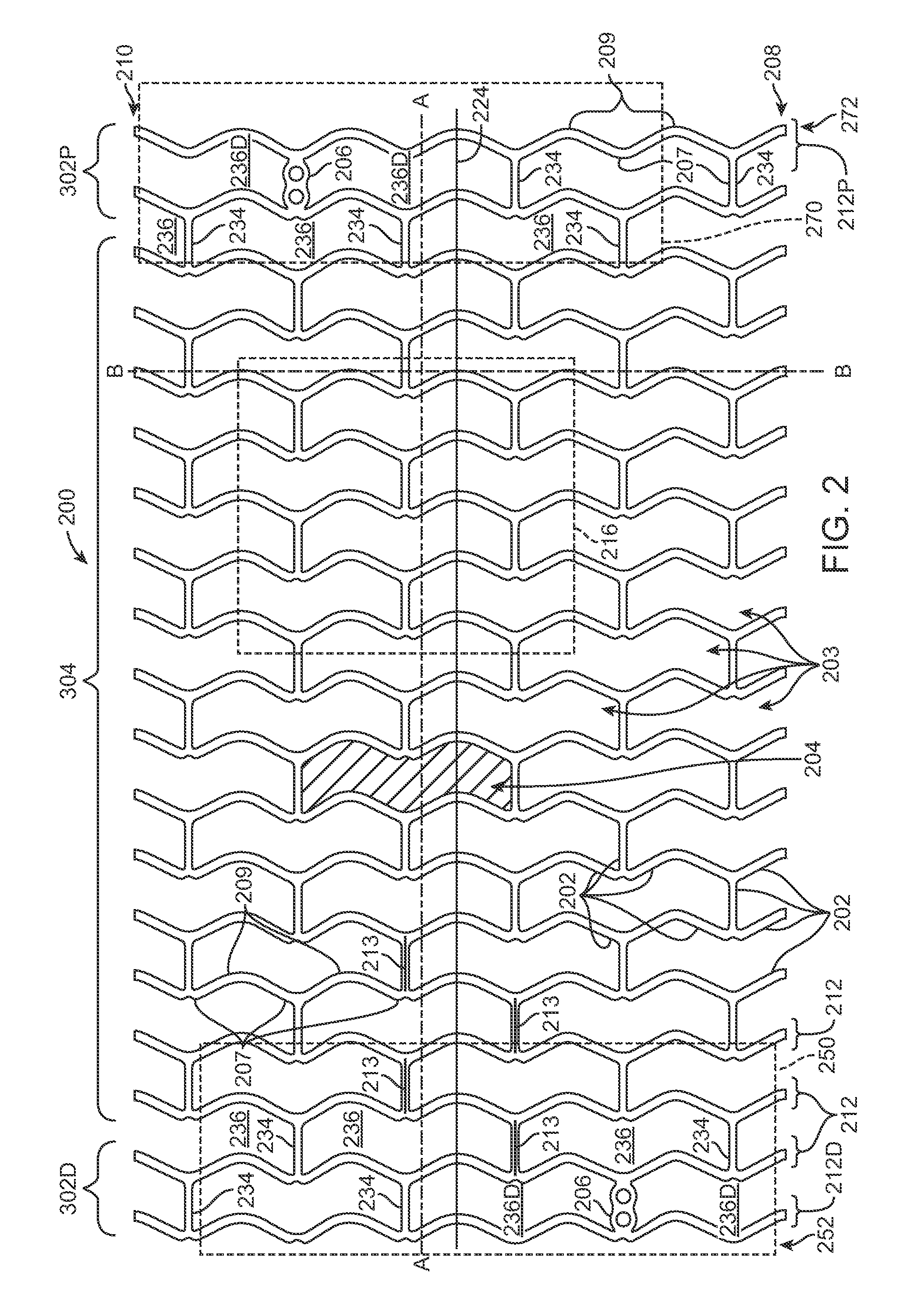
[0036]Referring now in more detail to the exemplary drawings for purposes of illustrating embodiments of the invention, wherein like reference numerals designate corresponding or like elements among the several views, there is shown in FIG. 1 a tube 100 that serves as a stent precursor construct in the sense that further processing is performed on the tube before the pattern of stent struts is cut formed from the tube.

[0037]After further processing of the tube 100, a pattern of struts is formed on the resultant tube by chemical etching, mechanical cutting, or laser cutting material away from the tube. Representative examples of lasers that may be used include without limitation excimer, carbon dioxide, YAG, and ultra fast lasers. The tube 100 is cylindrically-shaped with an outside diameter 105, an inside diameter 110, an outside surface 115, and a central axis 120.

[0038]The tube 100 is formed by extrusion of poly(L-lactide) (“PLLA”). In other embodiments, a tubular precursor constr...


PUM

PropertyMeasurementUnit
Angleaaaaaaaaaa
Angleaaaaaaaaaa
Strengthaaaaaaaaaa

Abstract

A strut pattern of an endoprosthesis includes a plurality of W-shape cells that define a tubular body, the W-shaped cells at the opposite ends of the tubular body have a modified configuration that is different than the W-shaped cells at the middle portion of the tubular body. At the distal end of the tubular body, the W-shaped cells have crests with axial positions that are axially spaced apart, and have troughs with circumferential positions that are spaced apart. At the intermediate and distal end of the tubular body, the W-shaped cells crests with axial positions that coincide and have troughs with circumferential positions that coincide. The strut pattern is cut from a tubular precursor construct made of PLLA that has been radially expanded and axially extended by blow molding.

Description

CROSS-REFERENCE TO RELATED APPLICATION[0001]The present application is a continuation-in-part of application Ser. No. 12 / 114,608, filed May 2, 2008, the entire disclosure of which is incorporated herein by reference.FIELD OF THE INVENTION[0002]Briefly and in general terms, the present invention generally relates to coating a medical device, more specifically, to a system and method for coating a stent.BACKGROUND OF THE INVENTION[0003]In percutaneous transluminal coronary angioplasty (PTCA), a balloon catheter is inserted through a brachial or femoral artery, positioned across a coronary artery occlusion, and inflated to compress against atherosclerotic plaque to open, by remodeling, the lumen of the coronary artery. The balloon is then deflated and withdrawn. Problems with PTCA include formation of intimal flaps or torn arterial linings, both of which can create another occlusion in the lumen of the coronary artery. Moreover, thrombosis and restenosis may occur several months after ...

Claims


Application Information

Patent Timeline
IPC IPC(8): A61F2/06B28B1/48
CPCA61F2/0077A61F2/91A61F2/915A61F2002/91575A61F2210/0004B29D23/00B29C53/02B29C55/26B29C67/0014B29C2793/0009B29L2031/7534A61F2250/0067
Inventor YANG, ARLENE SUCYJOW, KEVINMORRISON, ANDREA DAWNLIMON, TIMOTHY A.
Owner ABBOTT CARDIOVASCULAR
Why Eureka
Try Eureka