Eureka AIR delivers breakthrough ideas for toughest innovation challenges, trusted by R&D personnel around the world.

Method for Capturing Mercury from Flue Gas

Active Publication Date: 2010-01-28
SRINIVASACHAR SRIVATS +1
View PDF18 Cites 41 Cited by
  • Summary
  • Abstract
  • Description
  • Claims
  • Application Information

AI Technical Summary

Benefits of technology

[0023]A method of the present invention consists of injecting the sorbent (consisting of at least some carbonaceous material) into the flue gas where the flue gas temperature is at a value above about 1100° F. and below about 2000° F. Injecting the sorbent at the locations corresponding to this temperature range, rather than further downstream at a cooler temperature, provides increased residence time for contact between the flue gas and the sorbent resulting in increased mercury capture and improved sorbent utilization. This invention overcomes limitations of the aforementioned methods including the ability to remove mercury from flue gases with a high efficiency in:
[0026]High sulfur trioxide environments, which are created when SO3 is injected for flue gas conditioning for improving ESP performance with high resistivity fly ash;
[0033]It is hypothesized that the first step in the sorption of gas phase mercury is the conversion of elemental mercury to oxidized / halogenated mercury species. This step is kinetically limited and is more effective at higher temperatures. In the flue gas path once the activated carbon sorbent is injected into the flue gas at a location such as in the superheater / reheater section or economizer section, some of the sorbent particles would be deposited on boiler heat transfer surfaces that are significantly lower temperature than the flue gas. The lower temperature should help the PAC to survive in the high-temperature flue gas stream. Also, the lower temperature allows the particles to act as sites for adsorption and capture of the halogenated mercury species. Once the halogenated mercury species is adsorbed it would be require a much higher temperature to desorb than elemental mercury. Thus the adsorbed halogenated mercury species would be retained by the activated carbon sorbent particles.
[0035]The invention dramatically improves performance of carbonaceous sorbents for mercury control compared to the previous methods.
[0039]Injecting the sorbent at the locations indicated above, rather than further downstream, provides both increased residence time for contact between the flue gas and the sorbent and higher temperatures for conversion of elemental mercury in flue gas to oxidized mercury species, a prerequisite for mercury capture, ultimately resulting in increased mercury capture and improved sorbent utilization.
[0041]Alternatively, to prevent the deterioration of the sorbent during injection at such elevated temperatures, the injection lances can themselves be cooled by having a water or air jacket so that the temperature within the lance does not increase above the reaction / ignition temperature of the sorbent components (typically the temperature should be kept below about 700° F.). Another method to keep temperatures below about 700° F. is to have a water spray injected with the sorbent into the lance, so that water evaporation as the sorbent moves through the lance will keep the temperature of the sorbent below its ignition point.

Problems solved by technology

In such cases, plain activated carbon performed poorly, i.e. the amount of material required to achieve desired capture efficiency was higher than when higher levels of halogen species were present in the flue gas.
Another problem with currently disclosed and used mercury control sorbents is their inability to perform with high efficiency in high concentration sulfur-containing flue gas.
These data show that not only does a lack of halogen components in the flue gas, but also the presence of sulfur species in the flue gas, adversely affect the performance of activated carbon in removing mercury species from the flue gas.
In this configuration, sorbent, such as activated carbon or halogenated activated carbon, is injected upstream of the hot-side ESP at around 500 to 700° F. Because of the short residence time for contact between the sorbent and the flue gases in such a configuration, mercury capture performance is poor.
Yet another problem with using activated carbon sorbents for mercury control is that when the spent carbon is mixed with the ash in the particulate collection device, it renders the ash unusable for some end-applications such as concrete.
Activated carbon because of its surface area and its propensity to adsorb the air entraining agents is deleterious.
The acceptable foam index value was around 250 for commercial fly ash sales, and so the injected sorbent proved to be deleterious for subsequent use of the ash for concrete applications.
The high injection rates are likely to be expensive and also may affect the performance of the power plant components by depositing and fouling their surfaces.
Also the injection of large quantities of material may adversely affect the performance of particulate collection devices and may result in increased particulate emissions.
The process above is not very effective as it uses a raw carbonaceous material as the material for injection.
Therefore, the produced sorbent within the flue gas is not optimum, as it does not have a high activity and a high surface area.
While Chang et al. used a gas stream for contacting the raw carbonaceous material with temperatures in the range of 100 to 1400° C. for the purposes of activation, they did not anticipate the beneficial effects of injecting an engineered material such as activated carbon at high temperatures and did not identify a preferred temperature range for the purposes of removing the vapor phase contaminant such as mercury using activated carbon.
For the above reasons, Chang et al. does not provide an optimum temperature range for contacting activated carbon with gas streams containing contaminants such as mercury to maximize mercury capture by the activated carbon.
Consequently, the carbon particles can start oxidizing and burning within the injection lances, deteriorating the sorbent and potentially even destroying them, as well as potentially causing other operational problems such as local deposition, plugging and over-heating.
This is one additional challenge of using activated carbon sorbent for mercury control while injecting the sorbent at high temperatures.

Method used


Image

  • Method for Capturing Mercury from Flue Gas
  • Method for Capturing Mercury from Flue Gas
  • Method for Capturing Mercury from Flue Gas

Examples


Embodiment Construction

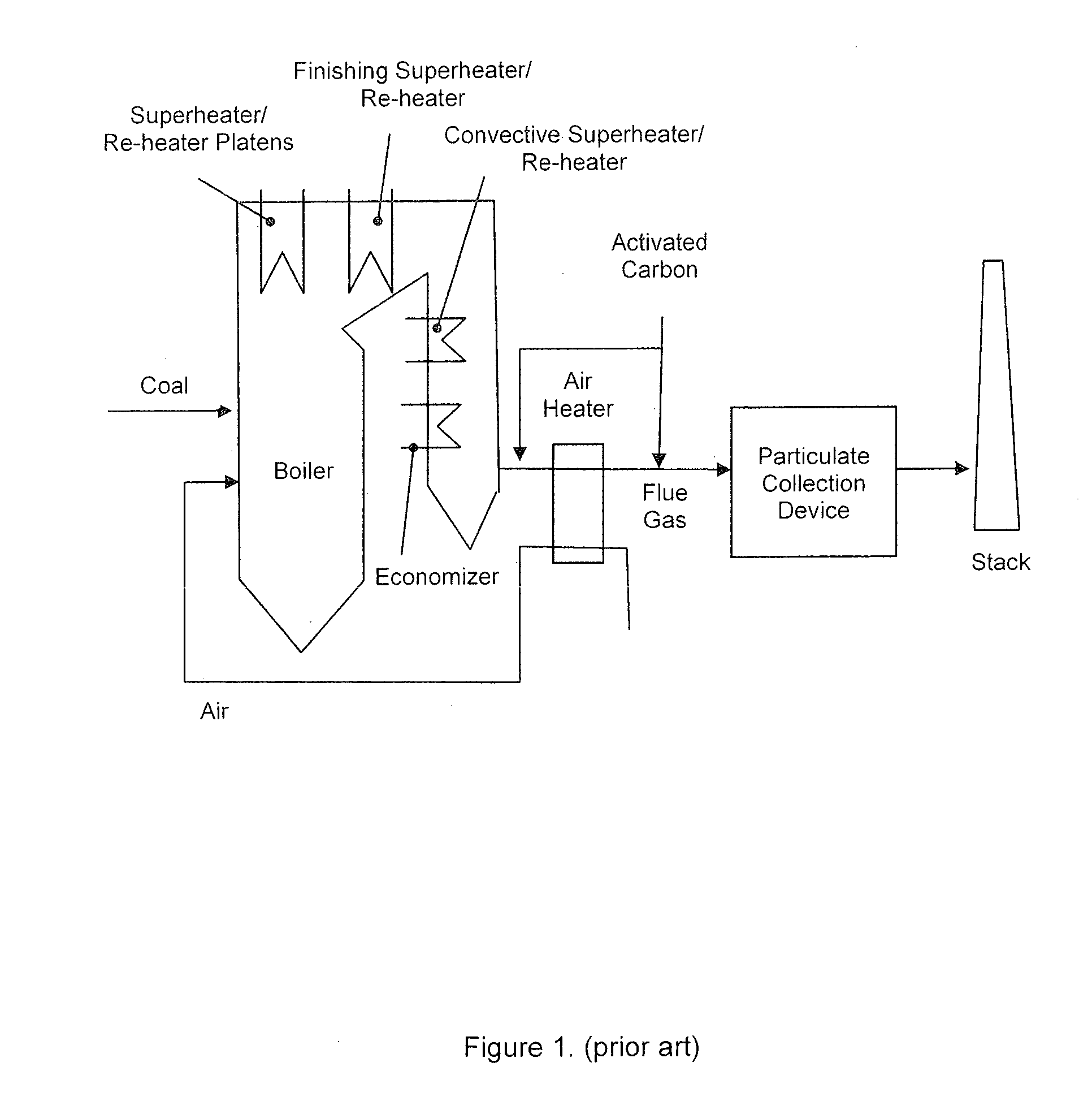
[0050]FIG. 1 provides an overview of a typical coal-fired power plant. The configuration, in this example, consists of a boiler, where water is evaporated to steam, followed by steam super-heater and re-heater sections (platens, finishing section, convective), an economizer section (where the boiler feed-water is pre-heated), and finally an air heater, where the combustion air is pre-heated. The combustion flue gas is cooled as it passes through each of these sections, transferring its heat to the water / steam stream on the other side of the heat exchangers. In a typical application, carbon sorbents are injected in the flue gas duct upstream of a particulate removal device such as a fabric filter or an electrostatic precipitator (FIG. 1), usually downstream of the air pre-heater and before the particulate removal device. The activated carbon used for such injection can be manufactured off-site from carbonaceous materials like coal, wood, or coconut shells.

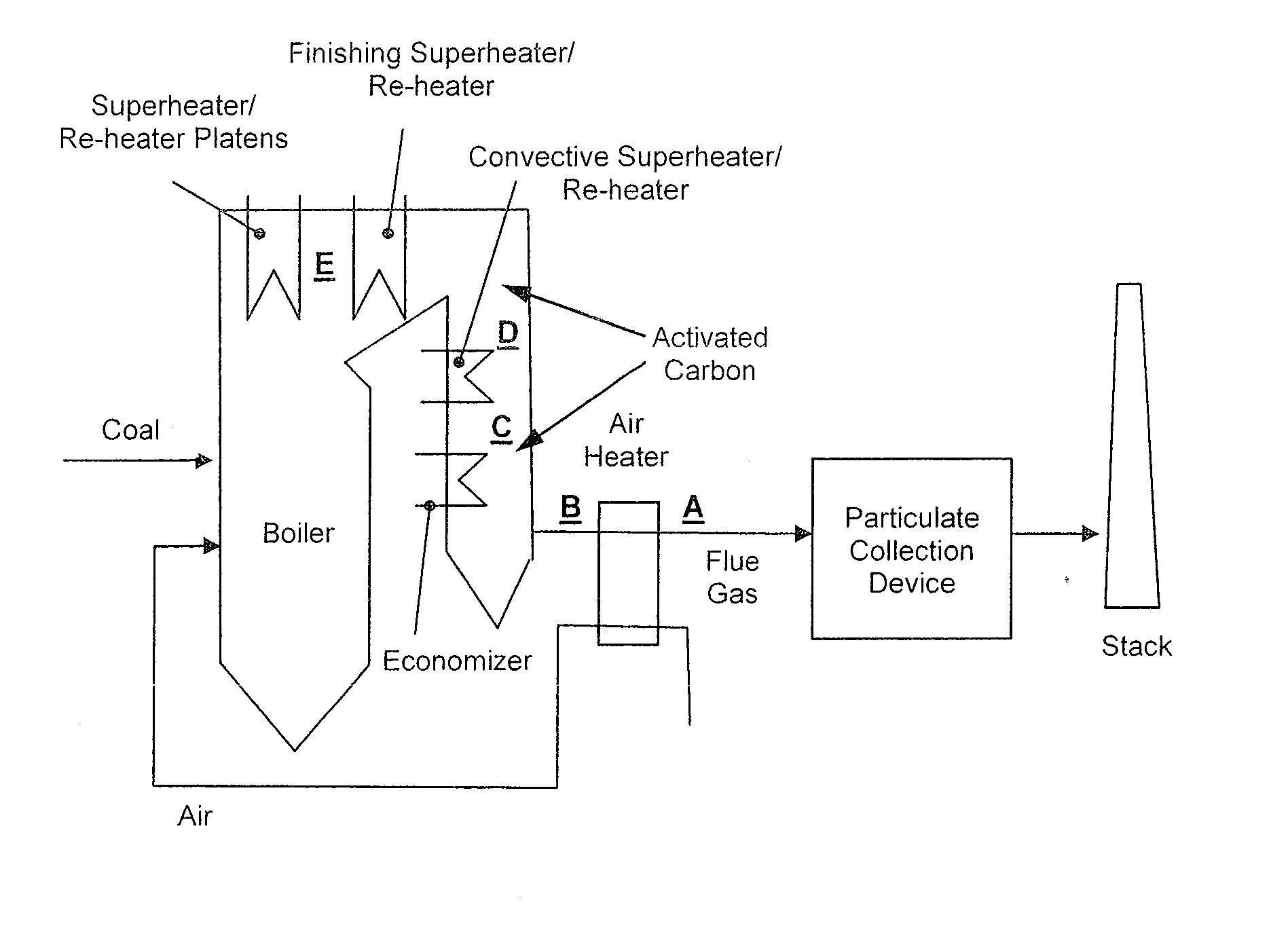
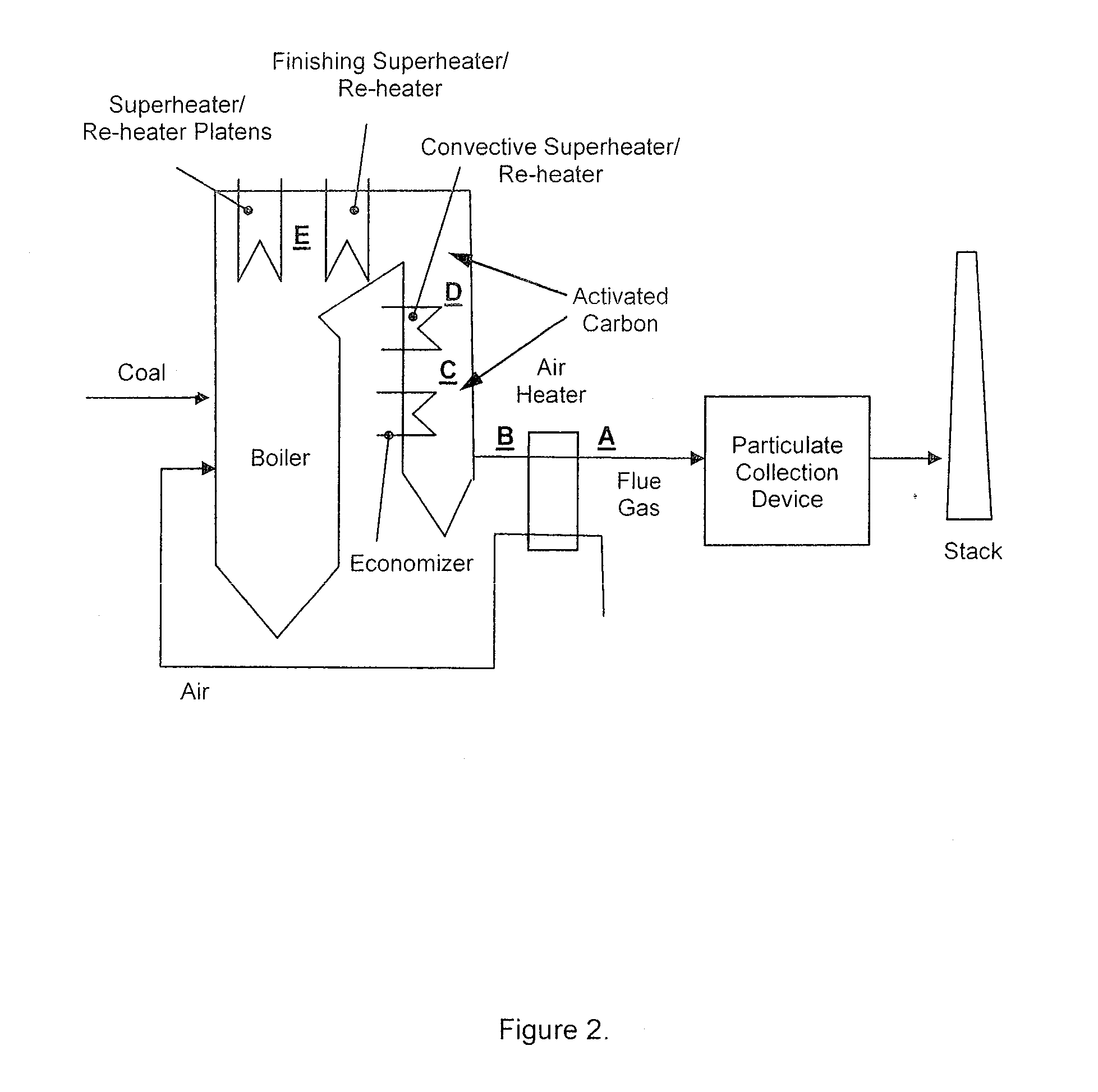
[0051]FIG. 2 shows exemplary...


PUM

PropertyMeasurementUnit
Temperatureaaaaaaaaaa

Abstract

The present invention relates to use of carbon-based sorbents such as activated carbon for controlling vapor phase mercury emissions in coal-fired power plant flue gases or waste incineration flue gases. The invention features new methods that improve the performance of carbonaceous sorbents for mercury control compared to the previous methods. One method consists of injecting the sorbent (consisting of at least some carbonaceous material) into the flue gas where the flue gas temperature is at a value above about 1100° F. and below about 2000° F. The invention also consists of injecting the sorbent within or upstream of an economizer section in a coal-fired power boiler. Injecting the sorbent at the locations indicated above, rather than further downstream, provides increased residence time for contact between the flue gas and the sorbent resulting in increased mercury capture, improved sorbent utilization, and improved fly ash properties.

Description

CROSS REFERENCE TO RELATED APPLICATION[0001]This application claims priority of Provisional Patent Application Ser. No. 61 / 083,095, filed on Jul. 23, 2008, the entire disclosure of which is incorporated herein by reference.FIELD OF THE INVENTION[0002]The present invention relates to the removal of mercury from the flue gases generated during the combustion of fossil fuels such as coal, or the combustion of solid wastes.BACKGROUND OF THE INVENTION[0003]Carbon-based sorbents such as activated carbon are currently used for controlling vapor phase mercury emissions in coal-fired power plant flue gases or waste incineration flue gases. In a typical coal-fired power plant, the configuration consists of a boiler, where water is evaporated to steam, followed by a steam super-heater section, a steam re-heater section, an economizer section (where the boiler feed-water is pre-heated), and finally an air heater, where the combustion air is pre-heated (FIG. 1). The combustion flue gas is cooled...

Claims


Application Information

Patent Timeline
IPC IPC(8): B01D53/64B01D53/02
CPCB01D53/10B01D2253/102B01D2257/602F23J2219/60F23J2215/60F23J2219/30F23J15/003
Inventor SRINIVASACHAR, SRIVATSBENSON, STEVEN A.
Owner SRINIVASACHAR SRIVATS
Why Eureka
Eureka Blog
Learn More