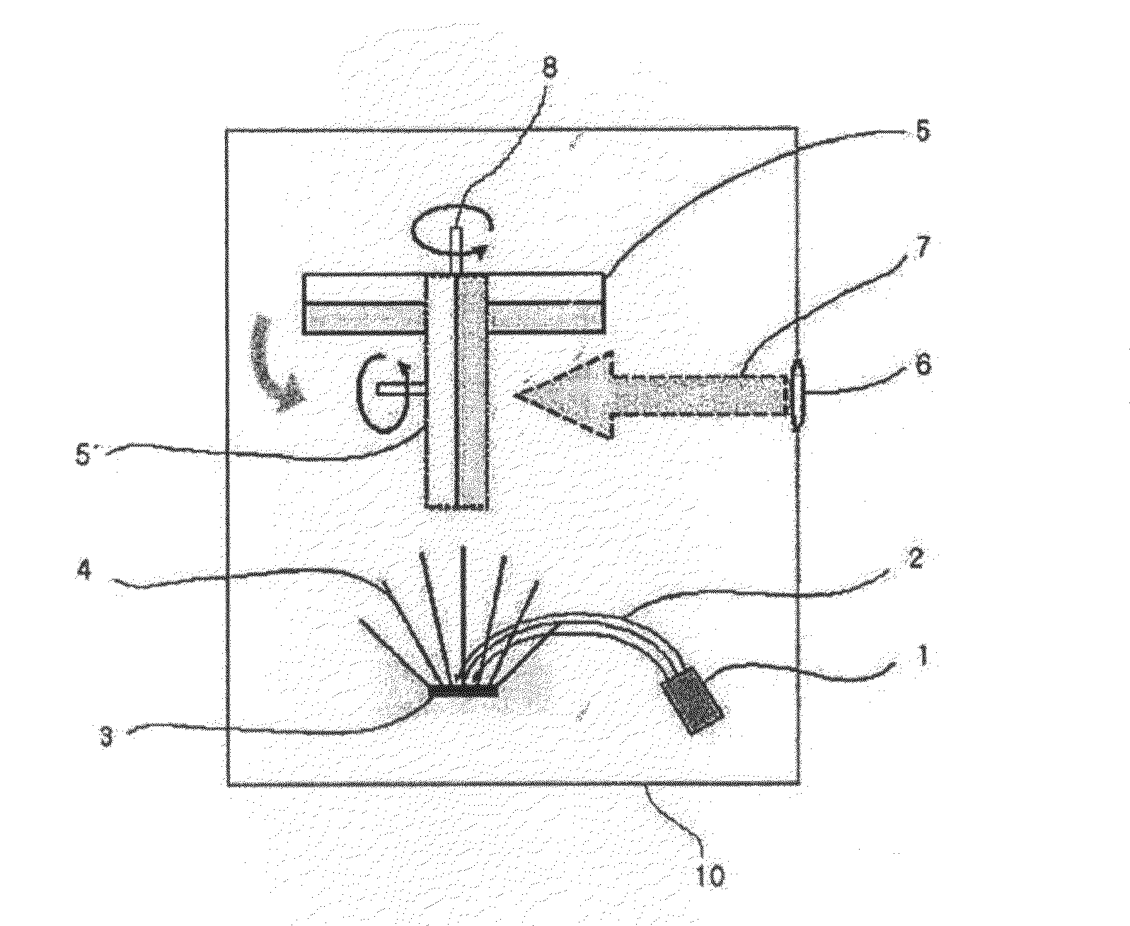
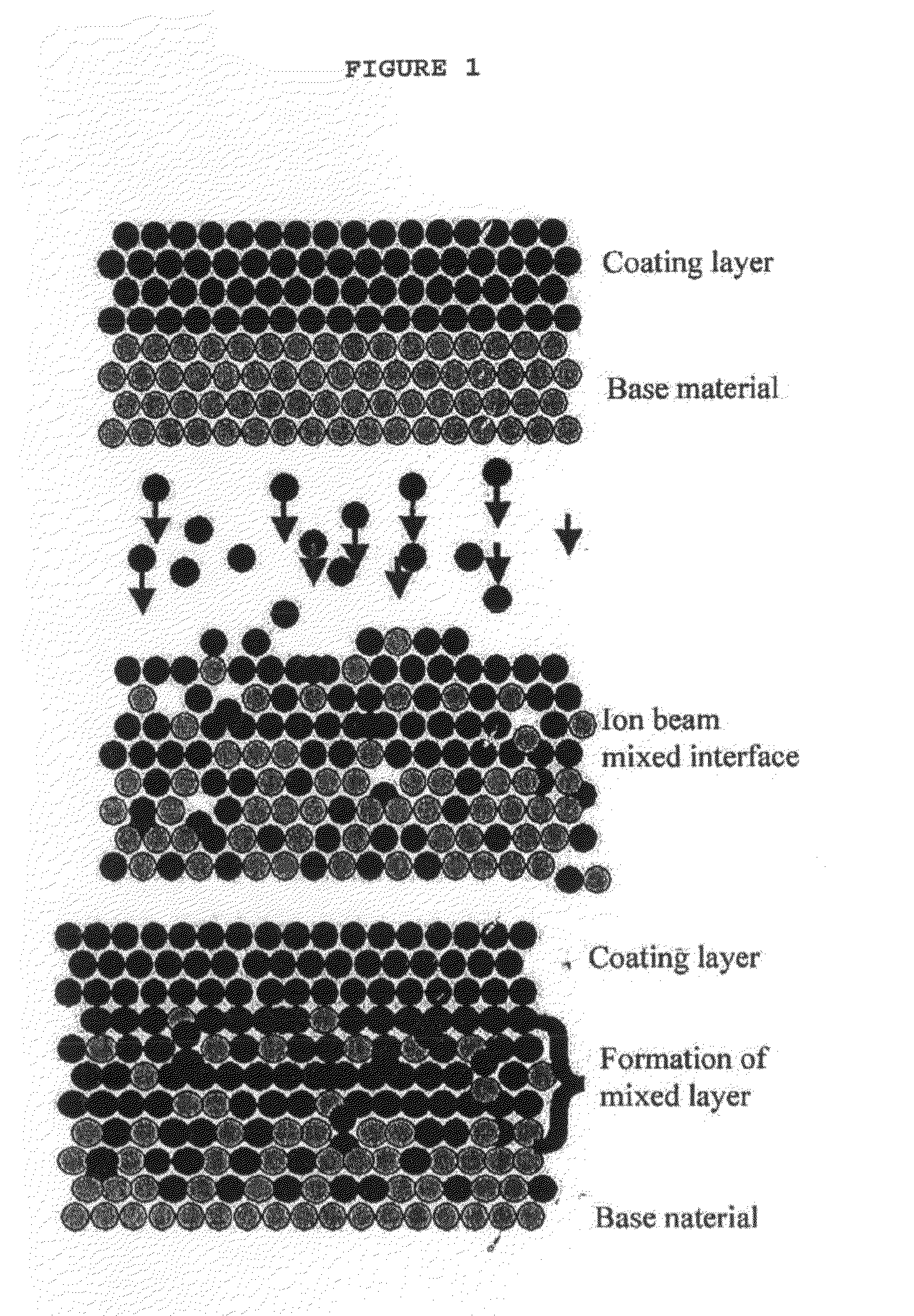
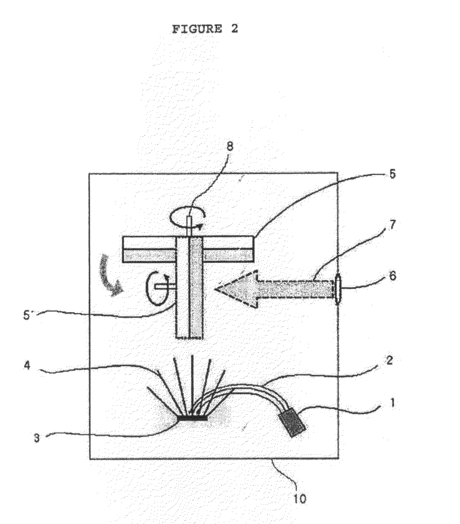
Coating and ion beam mixing apparatus and method to enhance the corrosion resistance of the materials at the elevated temperature using the same

a technology of mixing apparatus and ion beam, which is applied in the direction of vacuum evaporation coating, coating, electrolysis components, etc., can solve the problems of human existence being threatened, low danger, and the selection of the material used in the apparatus for performing the process becoming the most important issue, so as to improve the adhesion and improve the resistance to thermal stresses

Inactive Publication Date: 2010-02-11
KOREA HYDRO & NUCLEAR POWER CO LTD +1
View PDF7 Cites 0 Cited by
  • Summary
  • Abstract
  • Description
  • Claims
  • Application Information

AI Technical Summary

Benefits of technology

[0010]As described above, in the samples fabricated using the ceramic coating and ion beam mixing apparatus according to the present invention, the adhesion is improved, and the metallic base material is reinforce

Problems solved by technology

Recently, according to the so-called green house effect, which is the result of carbon dioxide discharge, a global warming phenomenon is rapidly progressing, so that a serious natural disaster occurs, thereby the existence of human beings is threatened.
The above process has been considered to be an influential method in that heat is stably supplied at a temperature of 950° C. or more and dangerousness is low.
However, the selection of the material used in an apparatus for performing the process is becoming the most important issue.
The reason is that a metal material must be used for high-temperature elasticity in the apparatus for the hydrogen producing process,

Method used


Image

  • Coating and ion beam mixing apparatus and method to enhance the corrosion resistance of the materials at the elevated temperature using the same
  • Coating and ion beam mixing apparatus and method to enhance the corrosion resistance of the materials at the elevated temperature using the same
  • Coating and ion beam mixing apparatus and method to enhance the corrosion resistance of the materials at the elevated temperature using the same

Examples


example 1

Analysis of SiC Thin Film Coated Using an Ion Beam Deposition Method

[0079]An SiC thin film was melted and vaporized and was then deposited on Inconel 690 by applying an electric power of 10 kW using an electron beam evaporative deposition method, and then Auger depth profiling was performed. The results of the Auger depth profiling are shown in FIG. 4.

[0080]As shown in FIG. 4, the SiC thin film was deposited on the surface of the Inconel 690, but the surface of the SiC thin film is covered with SiO2, because the SiO2 is easily formed, compared to the SiC. Therefore, difficulties in process control are likely to arise, because the coating process and the ion beam irradiation process are respectively performed in different reaction chambers, and it has been found that the coating process and the ion beam irradiation process must be performed in a single reaction chamber.

experimental example 1

Experiment on Change in Resistance of Thin Film to Sulfuric Acid Solution Corrosion by Ion Beam Irradiation

[0081]Inconel 680H samples were cut to a size of 20 mm×20 mm×5 mm, the entire surfaces thereof were polished to an average surface roughness (Ra) of 50 nm or less, and then SiC was deposited thereon. Next, the samples were put into a sulfuric acid solution having a concentration of 50% at 300° C., and then were corroded for 1 hour, in a state in which test samples were irradiated with an ion beam, and the other samples were not irradiated with an ion beam. After 1 hour had passed, the surface contours of the samples were observed. The results thereof are shown in FIG. 5.

[0082]As shown in FIG. 5, a thin film remains on the surface of the sample irradiated with an ion beam, but the thin film is almost peeled off of the surface of the sample not irradiated with the ion beam. The colors of the surface of sample appear to be different due to the difference in the thickness of the th...

experimental example 2

Experiment on Changes in Resistance to Electrical Etching of Thin Film Due to Ion Beam Irradiation

[0084]A circular SiC thin film having a diameter of 20 mm was deposited on the surface of Hastelloy X, which has a size of 20 mm×20 mm×5 mm and is polished to a surface roughness of 50 nm or less. Next, in the state in which testing samples were irradiated with an ion beam, and the other samples were not irradiated with the ion beam, the thin film reaches the surface of a material not coated with electrodes, and was electrolytically etched by applying a voltage of 4 V and a current of 0.4 A. After the thin film was etched, the surface contours of the samples were observed. The results thereof are shown in FIG. 6.

[0085]As shown in FIG. 6, in the sample not irradiated with the ion beam, a peeling phenomenon in the shape of flakes occurred at the corners of the coating layer of the sample. However, in the sample irradiated with an ion beam, the thin film was spread and the peeling phenomen...


PUM

PropertyMeasurementUnit
Temperatureaaaaaaaaaa
Thicknessaaaaaaaaaa
Energyaaaaaaaaaa

Abstract

The present invention relates, in general, to shoes for measuring the quantity of motion and a method of measuring the quantity of motion using the shoes and, more particularly, to artificial intelligence shoes, in which various numerical values (calorie consumption, body fat, and a pulse), measured by a walking sensor (23), a body fat measurement unit, and a pulse sensor (21) mounted in a shoe body, are displayed in real time on a display unit (32), so that a user can periodically check his or her quantity of motion, and in which calorie consumption and body fat are calculated on the basis of the user's body conditions, so that the precision thereof is high, and such quantity of motion numerical values can be transmitted to various types of external devices, thus enabling the user to periodically manage the quantity of motion thereof.

Description

TECHNICAL FIELD[0001]The present invention relates to a ceramic coating and ion beam mixing apparatus for improving corrosion resistance, and to a method of modifying an interface between a coating material and a base material.BACKGROUND ART[0002]Recently, according to the so-called green house effect, which is the result of carbon dioxide discharge, a global warming phenomenon is rapidly progressing, so that a serious natural disaster occurs, thereby the existence of human beings is threatened. Accordingly, human beings have become interested in hydrogen energy, which does not harm the environment, as a source of clean energy, and research and development into the clean energy has been focused on methods of economically producing hydrogen.[0003]A process for thermochemically producing hydrogen referred to as an Iodine-Sulfur cycle is considered the most efficient of the methods of producing hydrogen. In the process, hydrogen is produced by thermally decomposing sulfuric acid using ...

Claims


Application Information

Patent Timeline
IPC IPC(8): C23C14/34C23C14/00B29C71/04
CPCC23C14/5893H01J2237/3132C23C14/48H01J37/3233H01J2237/31701H01J2237/3165C23C14/505C23C14/30H01J2237/316H01J37/317C23C14/0635C23C14/5833C23C14/46C23C14/50
Inventor PARK, JAEWONPARK, CHANG-KUECHANG, JONGHWACHOI, BYUNGHOKIM, YONGWAN
Owner KOREA HYDRO & NUCLEAR POWER CO LTD
Why Eureka
Try Eureka