[0022]In view of the above, it is the task of the present invention to find a way to overcome the deficiencies of prior art and allow an improved control of the
dose rate (
dose per beam per
gray level) and relative placement of the beams in the
multi beam array in order to form an array of beams which, at its final position on the target, is undistorted and has an identical dose increment per
gray level (i.e. for equal “beam on” interval) and practically identical
beam shape. In other words, the task of the invention is to allow a very efficient
bitmap coding of the writing
data stream, which can be done in “real time” using an online
data preparation module, based on identical beams distributed on an ideal grid. According to the basic idea of the invention, the relative placement of the beams is accomplished by pre-
distortion of the array of apertures in the BAA (pattern definition device), and the
dose rate correction is done by adapting the sizes of apertures according to the
current density of the illuminating beam.
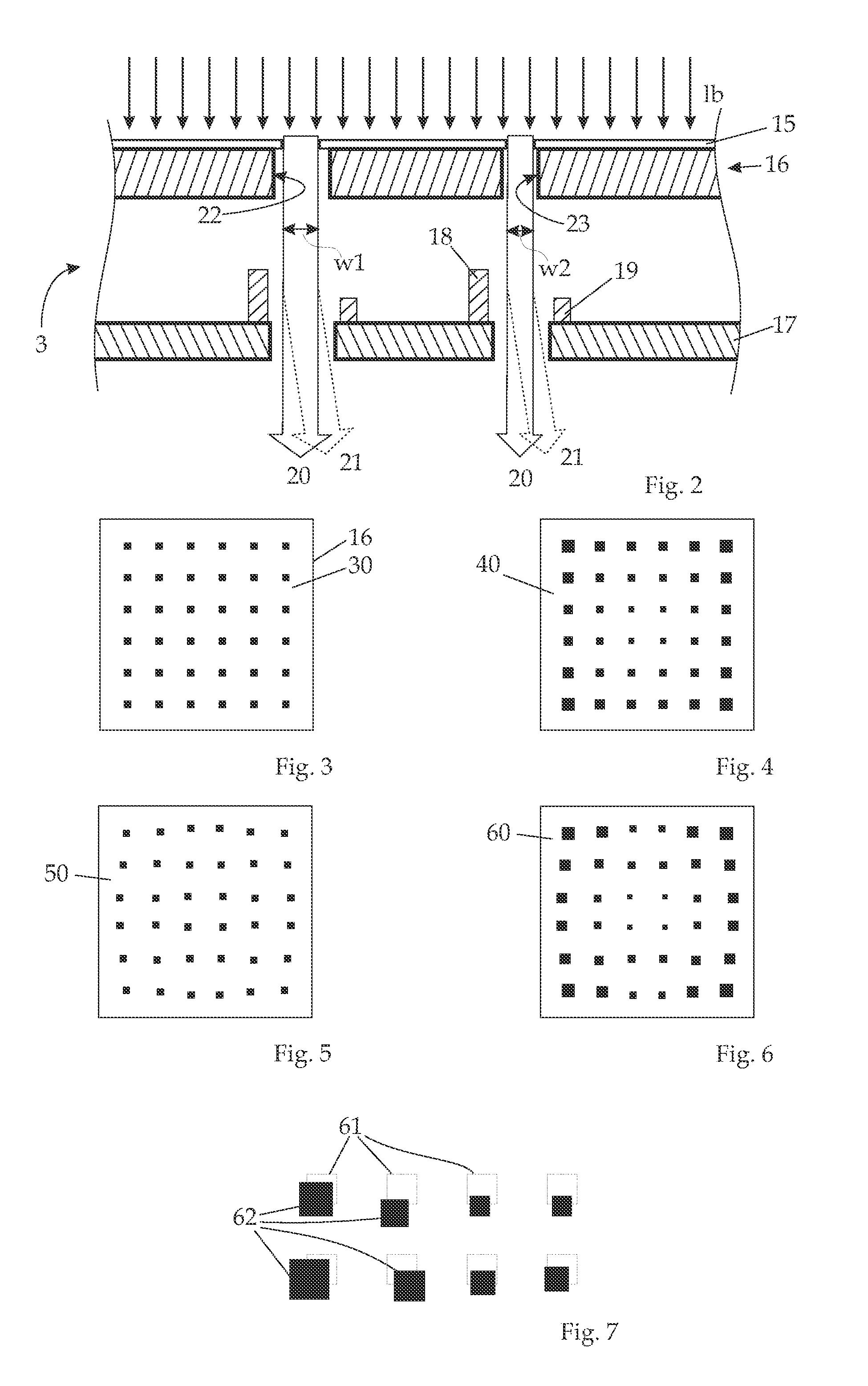
[0023]As has been well established in the state of the art, the
dose rate per beam is unavoidably influenced by the
local current density generated by the illuminating beam, which is generally a radial function of the distance from the
optical axis. The
distortion of the image caused by
distortion errors of the
projection system is as well generally a function of the radial distance (i.e., the distance from a center, usually the distance from the
optical axis). Therefore, a leveling of the
dose rate and relative position correction (pre-distortion) over the radial distance is highly desirable. Both,
current density variation and distortion can be pre-calculated quite accurately using state-of-the-art
charged particle optics calculation routines which include
space charge and very precise field calculation. Moreover, generally, the distortion of the image caused by distortion errors of the
projection system may be a function not only of the radial distance; rather, in particular when particle-optical components that do not have radial symmetry (such as multipole electrodes) the distortion may depend on the azimuthal angle as well.
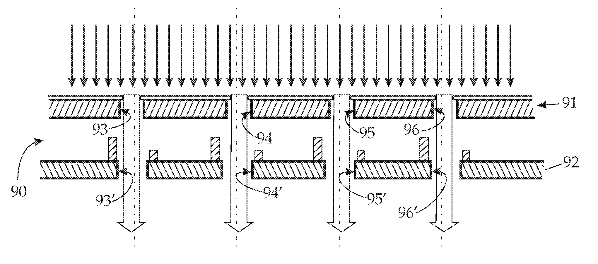
[0027]The present invention allows for an efficient correction of the mentioned beam and imaging defects by means of a suitable adjustment of position and / or size of the apertures in the aperture plate (this means that, preferably, the apertures have the same shape but may have varying size). Thus, the present invention enhances the precise lithographic definition of the image to be produced on the target, and ensures a
high resolution of the individual features of the image, independently of the relative position of the beams with respect to the optical axis. Furthermore, the invention allows an efficient
bitmap coding of the
dose distribution needed to produce the “as designed” structure on the substrate.
Bitmap coding is necessary to employ fast algorithms for transforming a designed pattern (for example given as GDSII file) into a
data stream that can be handled by the BAA and
data path elements. For high
throughput applications the BAA has generally a limited number of possible gray levels due to limited space for addressing lines and limited
clock speed of the ASIC structure embedded in the aperture membrane.
[0029]The positions of the openings in the blanking plate are chosen in correspondence with those of the apertures, usually with a sufficient size so as to allow clear passage of the beamlet even taking into account position deviation and tolerance of the corresponding aperture. In other words, the corresponding openings in the blanking means are arranged in an arrangement of openings; this arrangement may also be based on a basic arrangement but has deviations from the basic arrangement. The arrangement of the apertures of the aperture array may be chosen different to the arrangement of the corresponding openings of the blanking means, for instance to allow for a relaxed variation in the blanking openings as compared to the apertures. This is possible since it is the apertures which define the shape and position of the beamlets, whereas the blanking openings should allow passage to the beam anyway, while the blanking deflectors may introduce a deflection of the individual beamlet according to the desired pattern.

