Method and apparatus for the discretization and manipulation of sample volumes

Active Publication Date: 2010-02-18
UNIV OF WASHINGTON
View PDF13 Cites 85 Cited by
  • Summary
  • Abstract
  • Description
  • Claims
  • Application Information

AI Technical Summary

Benefits of technology

[0009]Embodiments of the present invention relate to new methods to discretize sample volume that is simple, robust, and versatile. In particular embodiments, a fluidic device partitions the sample not based on a steady state method such as the formation of droplet streams, but rather based on the interplay between fluidic forces, interfacial tension, channel geometry, and the fin

Problems solved by technology

However, these methods have limiting properties.
Furthermore, the droplets formed by either method are difficult to individually manipulate and analyze once formed.
In addition, neither of these methods would be well suited for the continuous monitoring that is necessary for in situ assays.
While this is a successful method of creating an array of spatially localized samples, the individual well filling can be a tedious endeavor.
Furthermore, human error can get in the way of dispensing homogeneous volumes.
However, the need for specialized dispensing equipment limits the flexibility of these microwell platforms, as well as raising the cost.
In addition, it is difficult to work with very small volumes (below 0.5 μL) because of the relatively high dispensing volumes of pipettes as well as problems with sample evaporation.
However, electrowetting mostly works for samples that are above the nanoliter scale and require sophisticated patterns of electrodes, greatly limiting its utility.
Patterned SAMs can

Method used


Image

  • Method and apparatus for the discretization and manipulation of sample volumes
  • Method and apparatus for the discretization and manipulation of sample volumes
  • Method and apparatus for the discretization and manipulation of sample volumes

Examples


example 1

Generation of Packets in Fluidic Harbors with Three Fluids

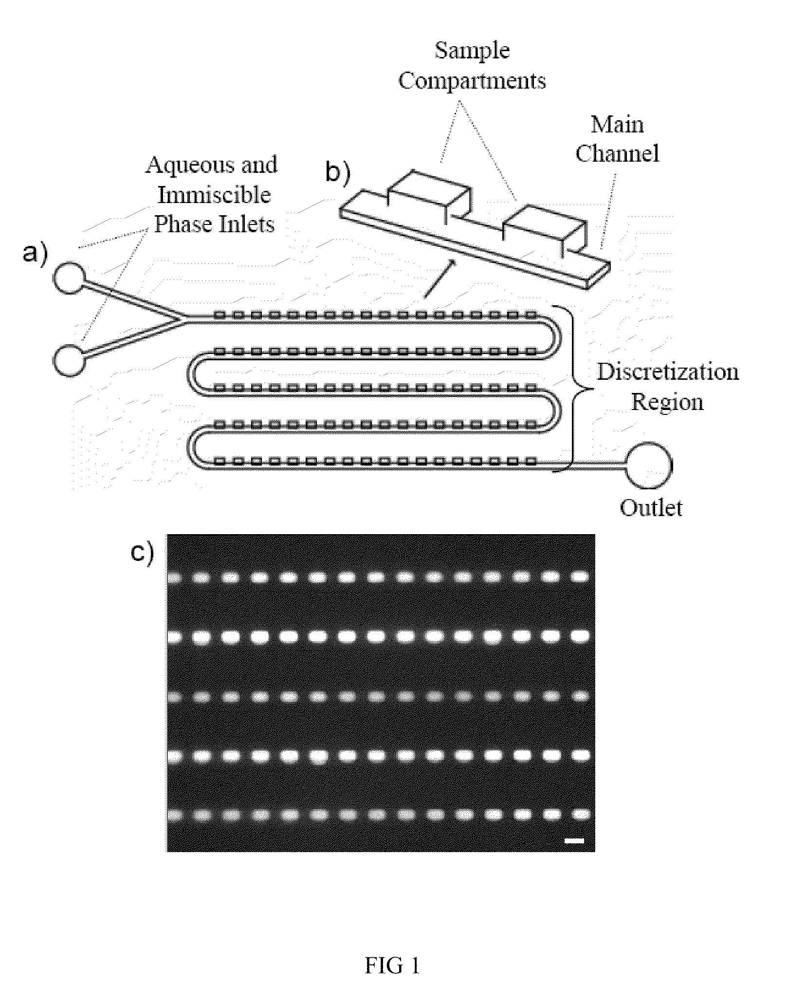
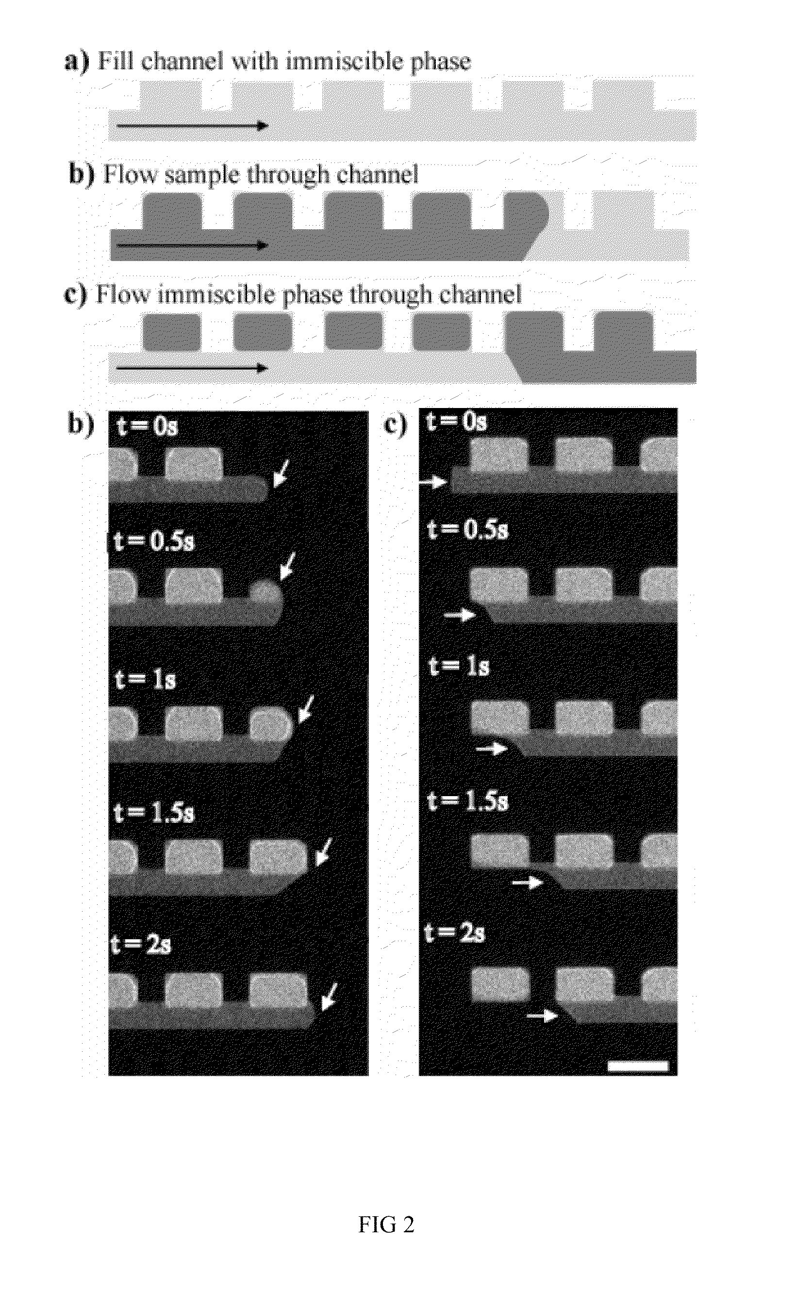
[0128]There is more than one method by which samples may be discretized using our device. In Fill Method #1 (FIG. 2), the device is first filled with a fluid that is immiscible with the sample phase to be discretized. Next, the sample phase is slowly introduced into the device. Following this, the immiscible phase is flown through the device a second time. In this last step, the sample phase is displaced from the main channel yet remains in the sample compartments, discretizing the sample phase into a volume that is determined primarily by the geometric dimensions of the sample compartment. Sometimes, the discretization can occur during the initial sample phase filling step. For biological assays where the sample is in an aqueous solution, Fill Method #1 would involve filling the device first with an immiscible phase (e.g. oil or Fluorinert), followed by the sample (aqueous phase), and finally the immiscible oil phase is flow...

example 2

Generation of Packets in Fluidic Harbors with Two Fluids

[0135]A second discretization method using our device is displayed in FIG. 4. In this method (Fill Method #2), the device is first filled with the sample phase. The sample phase is then discretized by flowing an immiscible phase through the main channel. For biological assays where the sample is in an aqueous solution, Fill Method #2 would involve filling the device first with the aqueous sample solution, followed by an immiscible phase, such as oil (e.g. mineral oil) or a fluorinated solvent (e.g. Fluorinert). Similar to Fill Method #1, as the immiscible phase flows through the device the sample phase is displaced from the main channel yet remains in the sample compartments. Again, the discretized sample volume is determined primarily by the dimensions of the sample compartment. With only two filling steps compared to the three of Fill Method #1, Fill Method #2 may be advantageous for certain applications.

[0136]In this example...

example 3

Generation of Packets in Fluidic Harbors with Fluids of Different Densities

[0140]An additional method that we have explored for sample discretization is based on exploiting a potential difference in the buoyancy of the sample and immiscible phases. In this method, the sample compartments reside either above or below the main channel, depending on whether the sample phase is more or less buoyant that the immiscible phase. If the sample phase is more buoyant than the immiscible phase, the compartments are placed above the main channel, if the sample phase is less buoyant than the immiscible phase, the compartments are below the main channel. FIG. 5 contains examples of potential discretization region geometries that may be used with this method. This method may be carried out by introducing either sample or immiscible phase into the device first, and then following the sequential flow outlined for Fill Methods 1 or 2. The specific flow sequence employed can be selected based on what i...


PUM

PropertyMeasurementUnit
Forceaaaaaaaaaa
Viscosityaaaaaaaaaa
Volumeaaaaaaaaaa

Abstract

Embodiments of the present invention relate to methods and apparatuses for the discretization and manipulation of sample volumes that is simple, robust, and versatile. It is a fluidic device that partitions a sample by exploiting the interplay between fluidic forces, interfacial tension, channel geometry, and the final stability of the formed droplet and/or discretized volume. These compartmentalized volumes allow for isolation of samples and partitioning into a localized array that can subsequently be manipulated and analyzed. The isolation of the discretized volumes along with the device's inherent portability render our invention versatile for use in many areas, including but not limited to PCR, digital PCR, biological assays for diagnostics and prognostics, cancer diagnosis and prognosis, high throughput screening, single molecule and single cell reactions or assays, the study crystallization and other statistical processes, protein crystallization, drug screening, environmental testing, and the coupling to a wide range of analytical detection techniques for biomedical assays and measurements. The minimal fluid interconnects and simple flow geometry makes the device easy to use and implement, economical to fabricate and operate, and robust in its operations.

Description

CROSS-REFERENCES TO RELATED APPLICATIONS[0001]The instant nonprovisional patent application claims priority to U.S. Provisional Patent Application No. 61 / 089,367, filed Aug. 15, 2008 and incorporated by reference in its entirety herein for all purposes.STATEMENT AS TO RIGHTS TO INVENTIONS MADE UNDER FEDERALLY SPONSORED RESEARCH OR DEVELOPMENT[0002]This invention was made with U.S. government support under R01 EB005197 awarded by the National Institutes of Health. The U.S. Government has certain rights in the invention.BACKGROUND OF THE INVENTION[0003]A first step in many chemical and biological applications is the discretization of sample volumes into small individual volumes for subsequent assays and analysis, where the assay or analysis can be of the same type or different types. The diverse variety of these applications highlights a need for different sample generation techniques with distinct advantages. Towards this end, several methods exist. Traditional methods of generating ...

Claims


Application Information

Patent Timeline
IPC IPC(8): C12Q1/68C12M1/00C12M1/34
CPCB01L3/502784B01L7/52B01L2300/0883B01L2300/165B01L2300/1827B01L2300/1861G01N2035/1034B01L2400/0633G01N35/08G01N2035/00356G01N35/10G01N2035/1032B01L2400/0439B01L3/502B01L2200/0642B01L2200/0673B01L2300/0877
Inventor CHIU, DANIEL T.COHEN, DAWN W.JEFFRIES, GAVIN D.M.
Owner UNIV OF WASHINGTON
Why Eureka
Try Eureka