
Composite stent having multi-axial flexibility

a flexible, composite technology, applied in the field of composite prostheses, can solve the problems of increased wall thickness, fracturing of metal-fabricated medical devices, and increased wall thickness of certain other implantable devices made from polymers, and achieve the effect of high radial strength

Inactive Publication Date: 2010-02-18
RAZMODICS LLC
View PDF37 Cites 52 Cited by
  • Summary
  • Abstract
  • Description
  • Claims
  • Application Information

AI Technical Summary

Benefits of technology

[0009]When a stent is placed into a vessel (particularly vessels such as the superficial femoral artery (SFA), iliac, popliteal, subclavian, pulmonary, renal, coronary arteries, etc.), the stent's ability to bend and compress is reduced. Moreover, such vessels typically undergo a great range of motion requiring stents implanted within these vessels to have an axial flexibility which allows for its compliance with the arterial movement without impeding or altering the physiological axial compression and bending normally found with positional changes.
[0013]An example of such a casting process is to utilize a dip-coating process. The utilization of dip-coating to create a polymeric substrate having such desirable characteristics results in substrates which are able to retain the inherent properties of the starting materials. This in turn results in substrates having a relatively high radial strength which is retained through any additional manufacturing processes for implantation. Additionally, dip-coating the polymeric substrate also allows for the creation of substrates having multiple layers.

Problems solved by technology

Some medical devices such as implantable stents which are fabricated from a metal have been problematic in fracturing or failing after implantation.
Moreover, certain other implantable devices made from polymers have exhibited problems such as increased wall thickness to prevent or inhibit fracture or failure.
In the example of a polymeric stent, the resulting stent may have imprecise geometric tolerances as well as reduced wall thicknesses which may make these stents susceptible to brittle fracture.
A stent which is susceptible to brittle fracture is generally undesirable because of its limited ability to collapse for intravascular delivery as well as its limited ability to expand for placement or positioning within a vessel.
Moreover, such polymeric stents also exhibit a reduced level of strength.
Brittle fracture is particularly problematic in stents as placement of a stent onto a delivery balloon or within a delivery sheath imparts a substantial amount of compressive force in the material comprising the stent.
A stent made of a brittle material may crack or have a very limited ability to collapse or expand without failure.
Although interventional therapy for SFA diseases using Nitinol stents is increasing, the SFA poses particular problems with respect to stent implantation because the SFA typically elongates and foreshortens with movement, can be externally compressed, and is subject to flexion.
Limitations of existing stents include, e.g., insufficient radial strength to withstand elastic recoil and external compression, kinking, and fracture.
However, it is suspected that these fractures may occur at a higher rate in the SFA than the other locations.
For example, because the SFA can undergo dramatic non-pulsatile deformations (e.g., axial compression and extension, radial compression bending, torsion, etc.) such as during hip and knee flexion causing significant SFA shortening and elongation and because the SFA has a tendency to develop long, diffuse, disease states with calcification requiring the use of multiple overlapping stents, stent placement, maintenance, and patency is difficult.
Moreover, overlapping of adjacent stents cause metal-to-metal stress points that may initiate a stent fracture.

Method used


Image

  • Composite stent having multi-axial flexibility
  • Composite stent having multi-axial flexibility
  • Composite stent having multi-axial flexibility

Examples


Embodiment Construction

[0040]When a stent is placed into a vessel (particularly vessels such as the superficial femoral artery (SFA), iliac, popliteal, subclavian, pulmonary, renal, coronary arteries, etc.), the stent's ability to bend and compress is reduced. Moreover, such vessels typically undergo a great range of motion requiring stents implanted within these vessels to have an axial flexibility which allows for its compliance with the arterial movement without impeding or altering the physiological axial compression and bending normally found with positional changes.

[0041]A composite stent structure having one or more layers of bioabsorbable polymers may be fabricated with the desired characteristics for implantation within these vessels. Each layer may have a characteristic that individually provides a certain aspect of mechanical behavior to the stent such that the aggregate layers form a composite polymeric stent structure capable of withstanding complex, multi-axial loading conditions imparted by...


PUM

PropertyMeasurementUnit
widthaaaaaaaaaa
distanceaaaaaaaaaa
diameteraaaaaaaaaa

Abstract

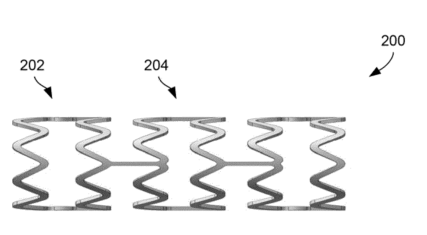
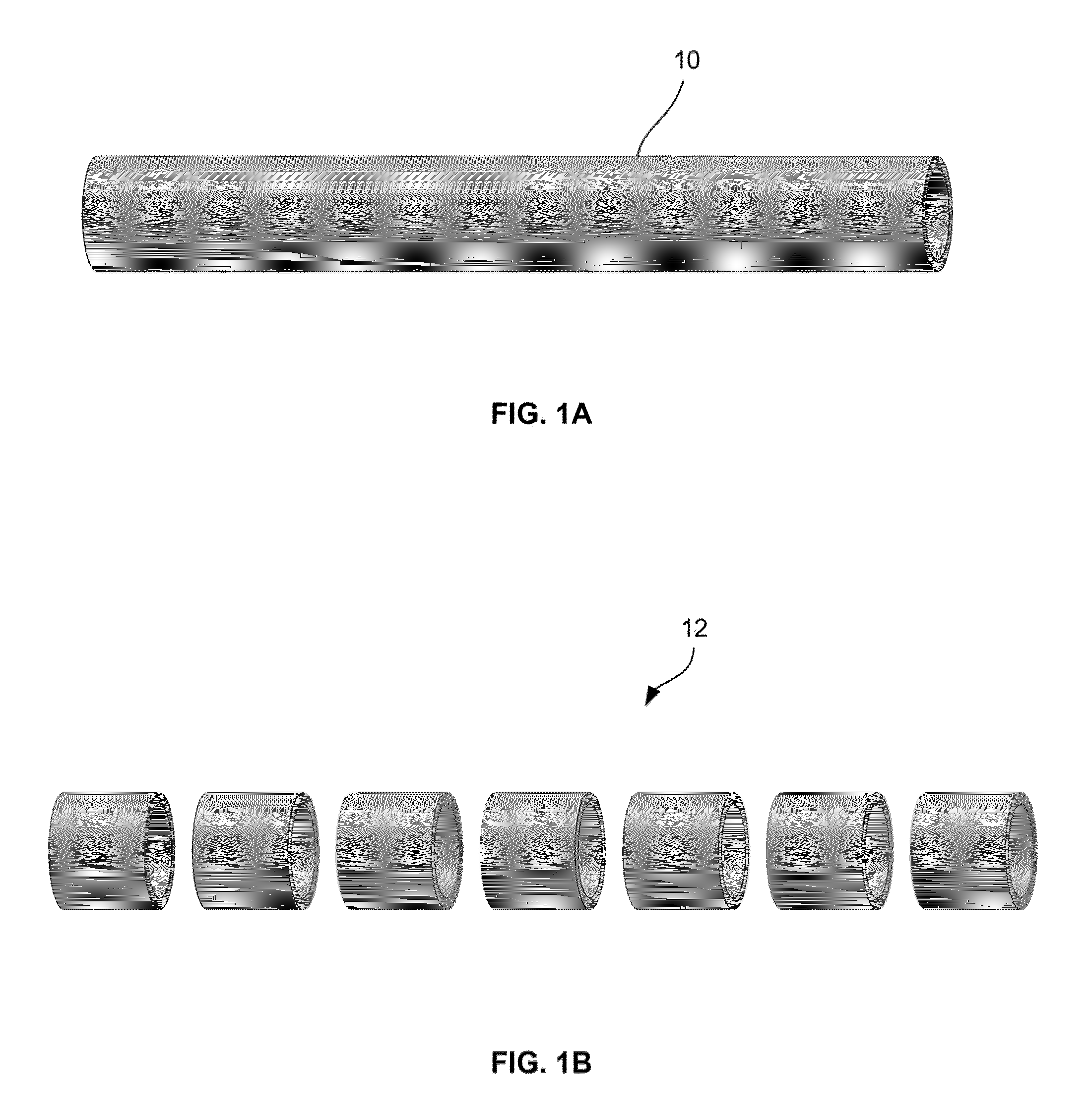
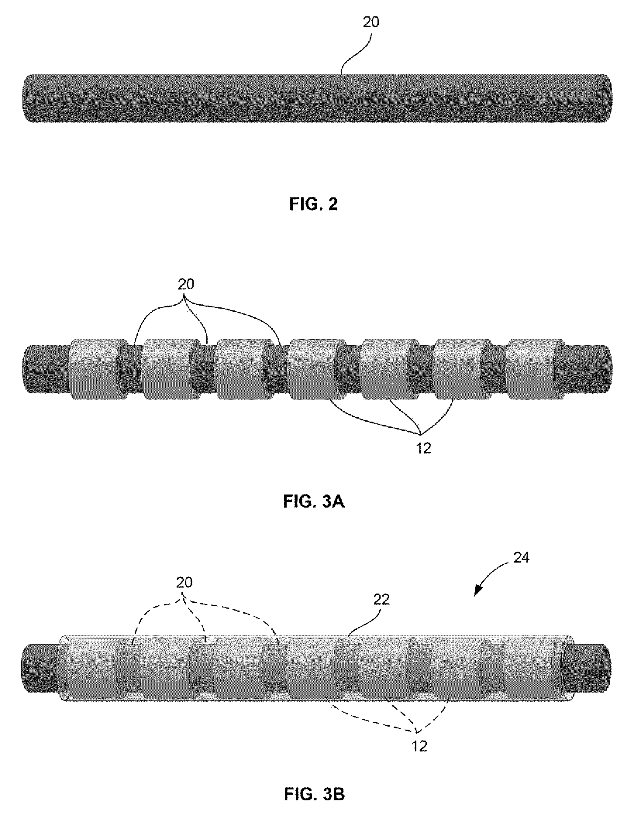
Composite stent structures having multi-axial flexibility are described where the composite stent may have one or more layers of bioabsorbable polymers fabricated with the desired characteristics for implantation within a vessel. A number of individual ring structures separated from one another may be encased between a base polymeric layer and an overlaid polymeric layer such that the rings are coupled to one another via elastomeric segments which enable the composite stent to flex axially and rotationally along with the vessel. Each layer may have a characteristic that individually provides a certain aspect of mechanical behavior to the composite stent such that the aggregate layers form a composite polymeric stent structure capable of withstanding complex, multi-axial loading conditions imparted by an anatomical environment such as the SFA.

Description

CROSS-REFERENCE TO RELATED APPLICATIONS[0001]This application claims the benefit of priority to U.S. Prov. Pat. App. 61 / 088,433 filed Aug. 13, 2008, which is incorporated herein by reference in its entirety.FIELD OF THE INVENTION[0002]The present invention relates generally to composite prostheses which are implantable within a patient. More particularly, the present invention relates to implantable tubular prostheses, such stents, which utilizes a composite structure having various geometries suitable for implantation within a patient.BACKGROUND OF THE INVENTION[0003]In recent years there has been growing interest in the use of artificial materials, particularly materials formed from polymers, for use in implantable devices that come into contact with bodily tissues or fluids particularly blood. Some examples of such devices are artificial heart valves, stents, and vascular prosthesis. Some medical devices such as implantable stents which are fabricated from a metal have been probl...

Claims


Application Information

Patent Timeline
Patent Type & Authority Applications(United States)
IPC IPC(8): A61F2/06B05D3/00B32B1/08A61F2/82
CPCA61F2/07A61F2/91A61F2002/826A61F2002/828A61F2210/0004A61F2210/0076B32B3/14B32B27/08B32B27/36Y10T428/139B32B1/08
Inventor RAMZIPOOR, KAMALSAUNDERS, RICHARD J.
Owner RAZMODICS LLC
Learn More