Complex Oxides Useful for Thermoelectric Energy Conversion

a thermoelectric energy and complex oxide technology, applied in the direction of oxide conductors, non-metal conductors, thermoelectric device manufacture/treatment, etc., can solve the problems of insufficient conversion efficiency of current thermoelectric materials based on bismuth telluride and/or semiconductors, inability of current thermoelectric systems to become widely used, toxic and hazardous popular thermoelectric materials tellurium and bismuth

Active Publication Date: 2010-03-04
RGT UNIV OF CALIFORNIA
View PDF14 Cites 18 Cited by
  • Summary
  • Abstract
  • Description
  • Claims
  • Application Information

AI Technical Summary

Benefits of technology

[0014]The thermoelectric system can further comprise a LaAlO3 (LAO) layer between the substrate and the first layer. The LAO layer can be of a thickness of less than about 20 nm.
[0015]The present invention also provides for a device comprising the thermoelectric system of the present invention, wherein the first complex oxide substrate contacts a first electrode and a second electrode. The present inve

Problems solved by technology

However, the conversion efficiencies for current thermoelectric materials based on bismuth telluride and/or semiconductors are not high enough to make them economically viable as compared to current energy conversion systems.
In addition, popular thermoelectric

Method used


Image

  • Complex Oxides Useful for Thermoelectric Energy Conversion
  • Complex Oxides Useful for Thermoelectric Energy Conversion
  • Complex Oxides Useful for Thermoelectric Energy Conversion

Examples


example 1

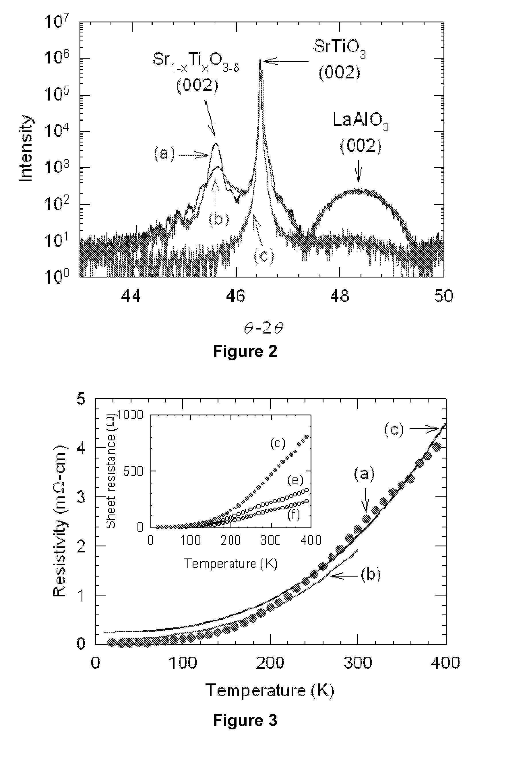
[0050]SrTiO3 (STO) is a cubic perovskite (Pm3m) with a bulk lattice parameter of 3.9056 Å. Out-of-plane lattice parameters of the films were characterized via x-ray diffraction using a Panalytical X'Pert MRD Pro 4-circle diffractometer for θ-2θ and rocking curve (ω) scans. All SLTO films grown were slightly distorted (˜1%) with the c-axis measuring 3.946 Å for typical 100 nm thick films.

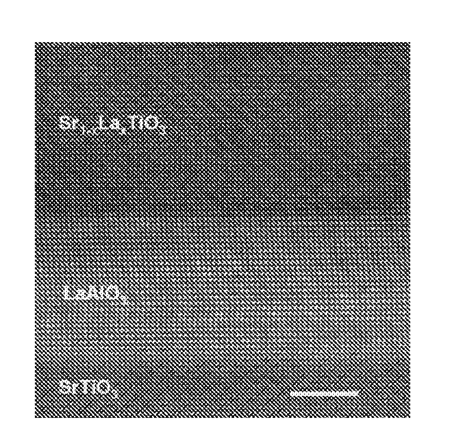
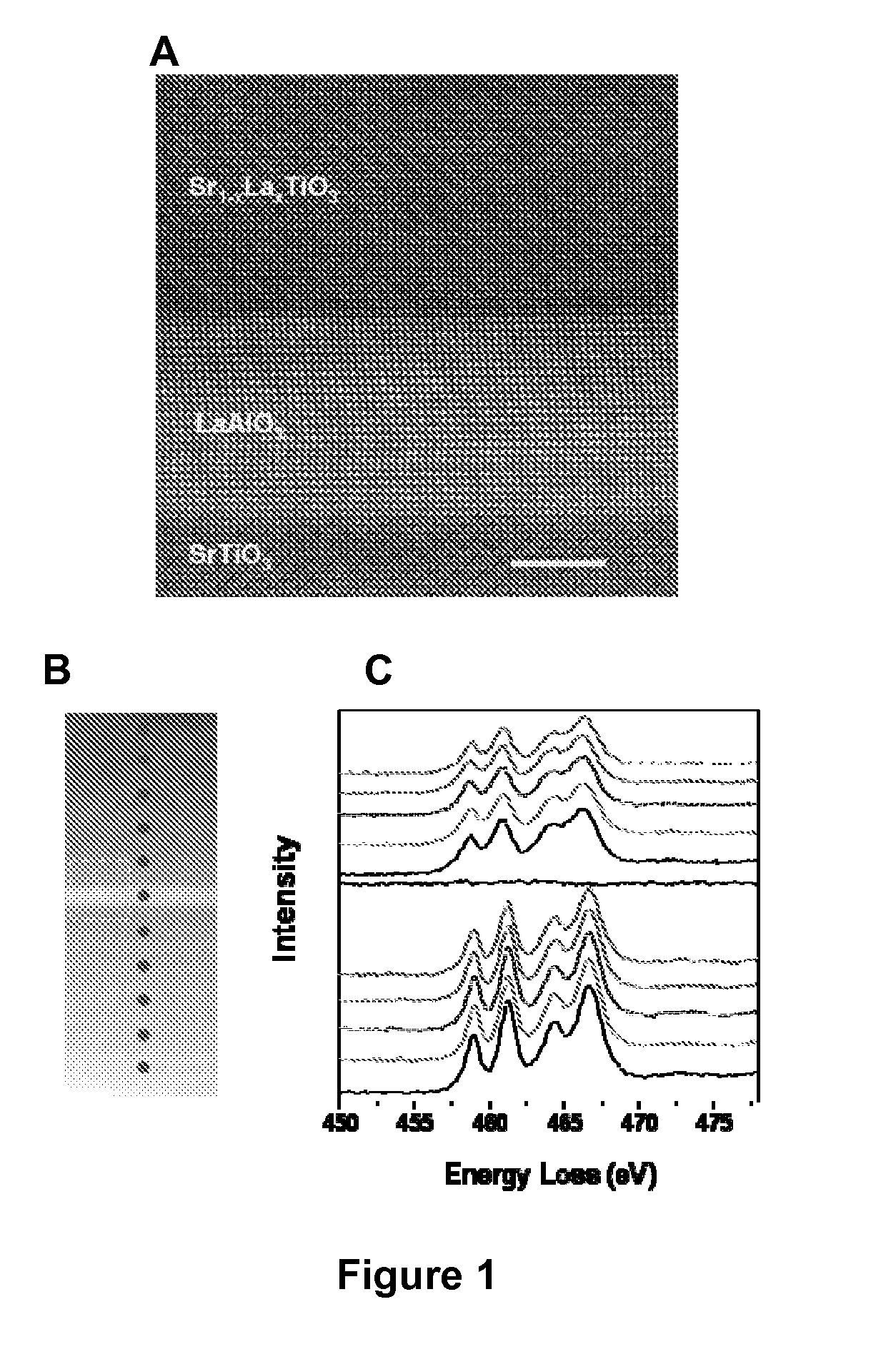
[0051]TEM characterization and electron energy-loss spectroscopy (EELS) were performed on an FEI Tecnai F20 equipped with a high-angle annular dark-field (HAADF) detector. The quasi-homoepitaxial films (αSLTO bulk=3.9057 Å) exhibited smooth surfaces and flat interfaces with the substrate, and maintained uniform thicknesses through the entire specimen. STEM EELS was performed across the SLTO / STO interface with an energy resolution of 0.7 eV.

[0052]In addition, RHEED pattern intensity oscillations of the STO 001 peak were visible throughout the growth of films to thicknesses of nearly 200 nm.

Targets, Su...

example 2

[0058]A laser molecular beam epitaxy (MBE) is used to deposit 50-nm-thick Lanthanum-doped SrTiO3 films from a target containing SrO, TiO2, and La2O3 on 5 mm×5 mm×500 μm single-crystalline SrTiO3 substrates with a 10-nm-thick LaAlO3 buffer layer. During the deposition, the substrate is kept at a temperature and a vacuum pressure of 450° C. and ˜10−7 Torr, respectively. The sample is cooled at about 10° C. / min and the pressure is maintained throughout the entire process. The laser energy density, the repetition rate, and the deposition rate are ˜1.6 J / cm2, and 1 Hz, respectively. The vacuum pressure is high enough to produce oxygen-deficient, Sr1-xLaxTiO3-δ (δ>0) films. The substrate is prepared by depositing a fully strained 10-nm LaAlO3 buffer layer on TiO2-terminated (001) SrTiO3 at 850° C. and ˜0.75×10⁻⁴ Torr. When the substrate is cooled after the LaAlO3 deposition, oxygen is purged into the chamber till atmospheric pressure. This minimize the oxygen vacancies that might be creat...


PUM


Abstract

The invention provides for a thermoelectric system comprising a substrate comprising a first complex oxide, wherein the substrate is optionally embedded with a second complex oxide. The thermoelectric system can be used for thermoelectric power generation or thermoelectric cooling.

Description

CROSS-REFERENCE TO RELATED APPLICATIONS[0001]This application claims priority as continuation application to PCT International Patent Application Ser. No. PCT / US2008 / 055720, filed on Mar. 3, 2008, which claims priority to U.S. Provisional Patent Application Ser. No. 60 / 892,820, filed on Mar. 2, 2007, respectively; which are hereby incorporated by reference.STATEMENT OF GOVERNMENTAL SUPPORT[0002]The invention described and claimed herein was made in part utilizing funds supplied by the U.S. Department of Energy under Contract No. DE-AC02-05CH11231. The government has certain rights in this invention.FIELD OF THE INVENTION[0003]This invention relates generally to complex oxides useful for thermoelectric energy conversion.BACKGROUND OF THE INVENTION[0004]Solid-state thermoelectric systems that can convert thermal energy to electrical energy directly are very attractive because they can be operated with various types of heat energy sources and they are environmentally benign. Furthermor...

Claims


Application Information

Patent Timeline
IPC IPC(8): H01L35/34H01L35/14H01L35/30H01B1/08
CPCH01L35/22H10N10/855
Inventor MAJUMDAR, ARUNAVARAMESH, RAMAMOORTHYYU, CHOONGHOSCULLIN, MATTHEW L.HUIJBEN, MARK
Owner RGT UNIV OF CALIFORNIA
Why Eureka
Try Eureka