Conductive Polymer Compositions in Opto-Electrical Devices

a technology of opto-electrical devices and conductive polymer compositions, which is applied in the direction of non-metal conductors, conductors, thermoelectric devices, etc., can solve the problems of lateral conduction and shorting between electrodes, very acidic compositions, and many significant problems, so as to increase the charge transfer, increase the conductivity, and facilitate the solution processing of compositions

Inactive Publication Date: 2010-03-11
CAMBRIDGE DISPLAY TECH LTD +1
View PDF20 Cites 17 Cited by
  • Summary
  • Abstract
  • Description
  • Claims
  • Application Information

AI Technical Summary

Benefits of technology

[0047]As an alternative to providing a blend of the optionally substituted TCNQ dopant and the polymer, the optionally substituted TCNQ dopant may be chemically bound to the polymer. This arrangement avoids the problems of finding a suitable solvent for both components and makes the dispersion of the dopant through the polymer more controllable. This allows for easy solution processing of the composition. Furthermore, a more intimate relation between the polymer and the dopant can be achieved and this can increase charge transfer between the polymer and dopant, thus increasing conductivity. Additionally, binding the dopant to the polymer prevents the dopant from diffusing through a device in use. It is advantageous for the dopant counter ion to remain in position for stabilizing the conductive polymer ion. This aids conduction.
[0048]Preferably the dopant is provided in a p...

Problems solved by technology

However, there are several significant problems.
For example, if a plurality of electrodes are provided in a device but only one continuous layer of conductive polymer extending over all the electrodes, then too high a conductivity can lead to lateral conduction and shorting between electrodes.
Without being bound by theory, one possible limitation on the lifetime of devices using the aforementioned PEDOT-PSS system is that the provision of such a large excess of PSS results in a composition which is very acidic.
This may cause ...

Method used


Image

  • Conductive Polymer Compositions in Opto-Electrical Devices
  • Conductive Polymer Compositions in Opto-Electrical Devices
  • Conductive Polymer Compositions in Opto-Electrical Devices

Examples


Embodiment Construction

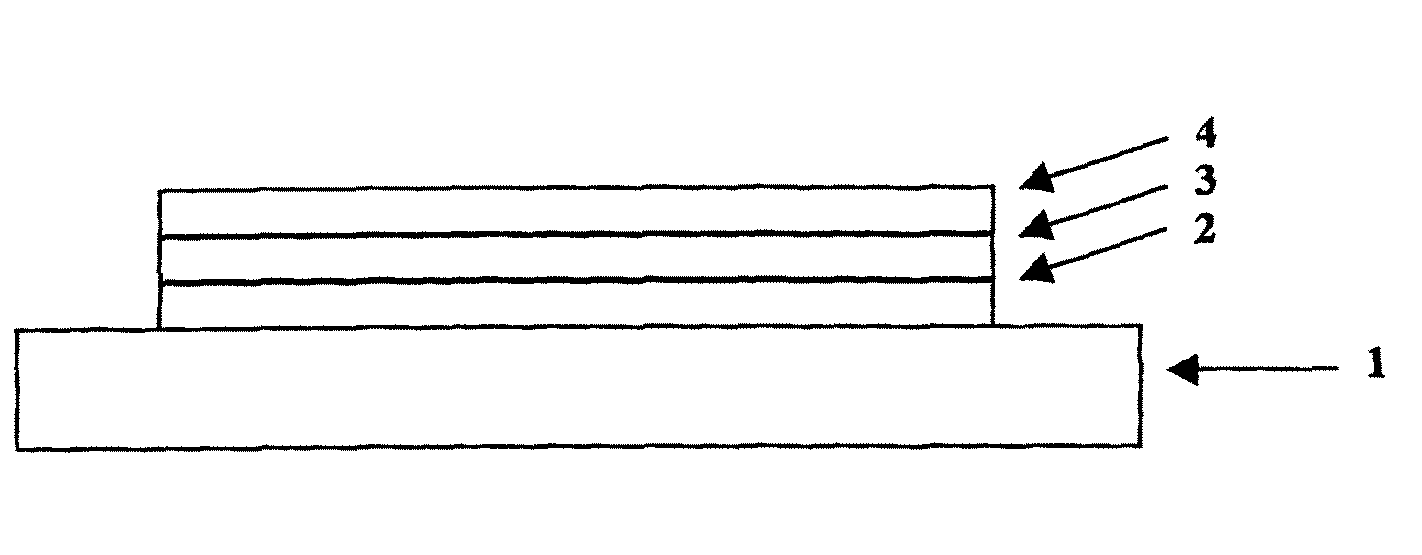
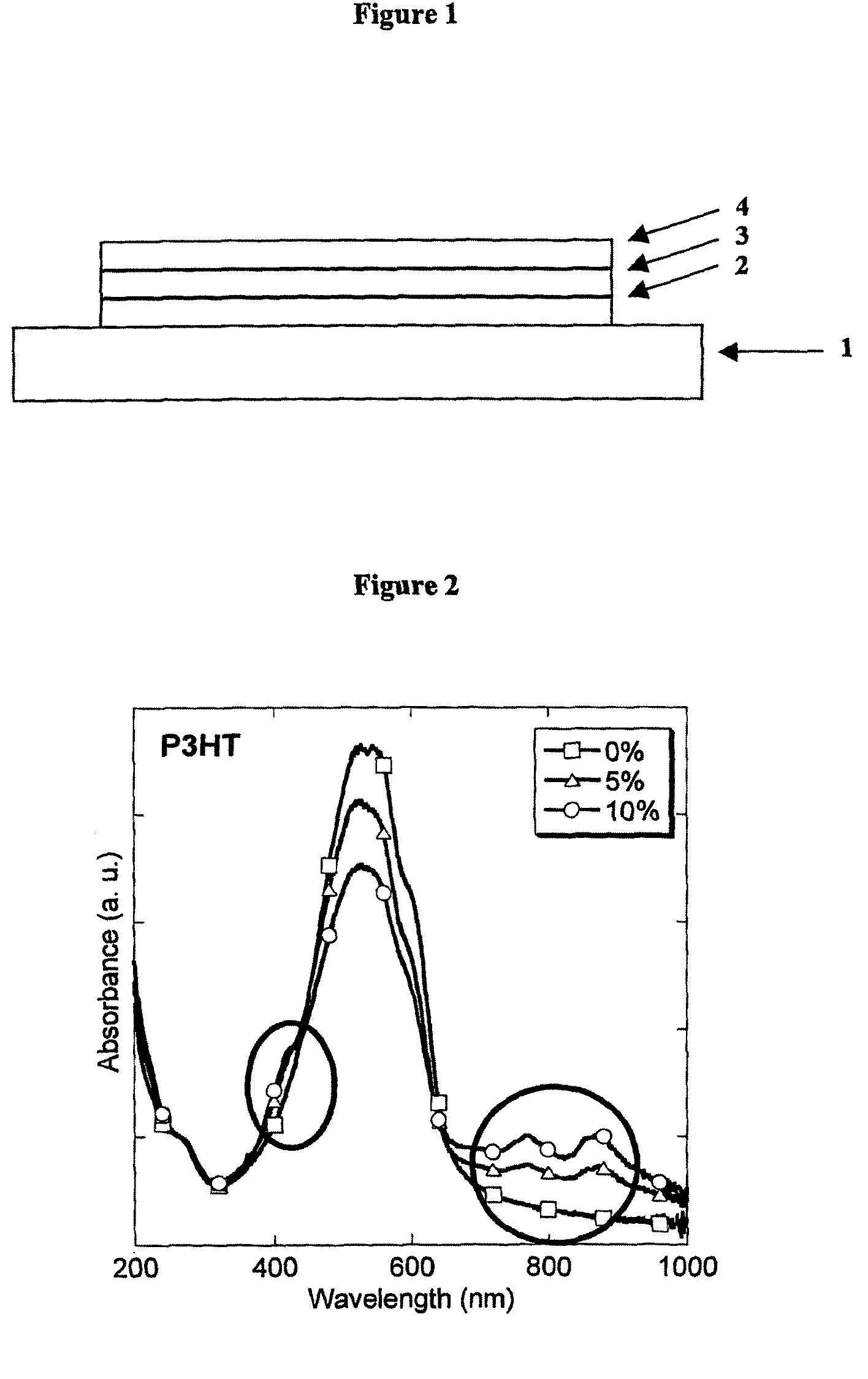
[0073]The device shown in FIG. 1 comprises a transparent glass or plastic substrate 1, an anode 2 of indium tin oxide and a cathode 4. An electroluminescent layer 3 is provided between anode 2 and cathode 4.

[0074]Further layers may be located between anode 2 and cathode 3, such as charge transporting, charge injecting or charge blocking layers.

[0075]In accordance with an embodiment of the present invention, a conductive hole injection layer formed of a conductive polymer composition is located between the anode 2 and the electroluminescent layer 3 to assist hole injection from the anode into the layer or layers of semiconducting polymer.

[0076]The hole injection layer may be made by mixing a fluorene-triaryl amine or thiophene co-polymer with F4TCNQ in a suitable solvent, such as toluene for instance. The resultant composition may be spin coated or ink jet printed to form a layer on the anode.

[0077]The hole injection layer located between anode 2 and electroluminescent layer 3 has a ...


PUM

PropertyMeasurementUnit
Energyaaaaaaaaaa
Energyaaaaaaaaaa
Energyaaaaaaaaaa

Abstract

A conductive polymer composition comprising: a polymer having a HOMO level greater than or equal to −5.7 eV and a dopant having a LUMO level less than −4.3 eV.

Description

FIELD OF INVENTION[0001]This invention relates to conductive polymer compositions and opto-electrical devices comprising conductive polymer compositions.BACKGROUND OF INVENTION[0002]One class of opto-electrical devices is that using an organic material for light emission or detection. The basic structure of these devices is a light emissive organic layer, for instance a film of a poly (p-phenylenevinylene) (“PPV”) or polyfluorene, sandwiched between a cathode for injecting negative charge carriers (electrons) and an anode for injecting positive charge carriers (holes) into the organic layer. The electrons and holes combine in the organic layer generating photons. In WO 90 / 13148 the organic light-emissive material is a polymer. In U.S. Pat. No. 4,539,507 the organic light-emissive material is of the class known as small molecule materials, such as (8-hydroxyquinoline) aluminium (“Alq3”). In a practical device one of the electrodes is transparent, to allow the photons to escape the de...

Claims


Application Information

Patent Timeline
IPC IPC(8): H01L51/10H01L51/40H01B1/12
CPCC08G73/0266C08K5/315C08L25/18C08L79/00H01B1/127H01L51/0039H01L51/5088H01L51/004H01L51/0043H01L51/5052C08L2666/04H10K85/115H10K85/141H10K85/151H10K50/155H10K50/17H10K50/12
Inventor BURROUGHES, JEREMYYIM, KENG HOONGKIM, JI-SEON
Owner CAMBRIDGE DISPLAY TECH LTD
Why Eureka
Try Eureka