Plasma Generation System and Plasma Generation Method
- Summary
- Abstract
- Description
- Claims
- Application Information
AI Technical Summary
Benefits of technology
Problems solved by technology
Method used
Image

Examples
embodiment 1
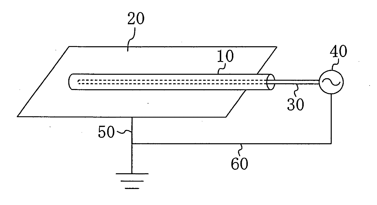
[0043]A plasma generation system according to embodiment 1 is shown in FIG. 1. The plasma generation system is a system for generating plasma in the cavity of a narrow tube 10. The plasma generation system includes a first electrode 30 which is to be inserted into the cavity of the narrow tube 10 (already inserted in FIG. 1), a second electrode 20 located outside the narrow tube 10, and a power supply 40 for applying an alternating voltage or pulse voltage between the first electrode 30 and the second electrode 20.
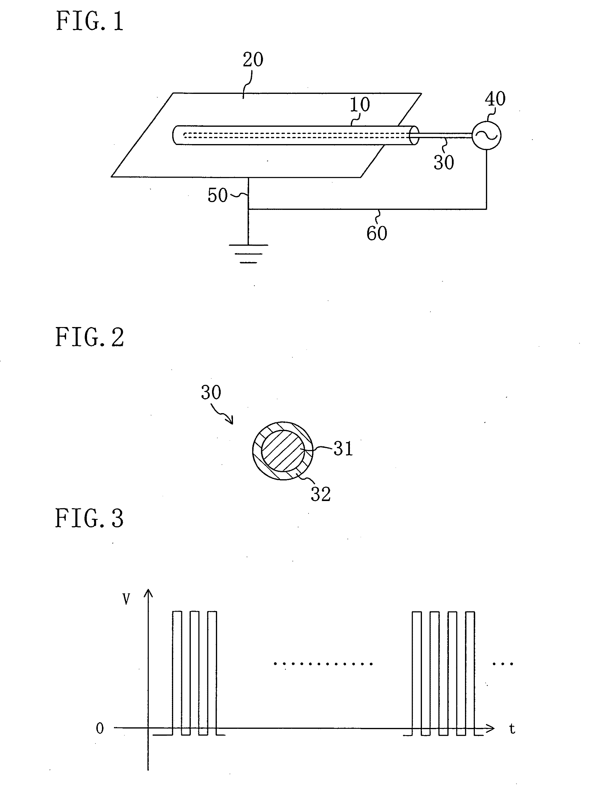
[0044]The first electrode 30 is formed by, as shown in FIG. 2, a conductive member 31 and a clad 32 of insulator or dielectric covering the surface of the conductive member 31. The conductive member 31 may be made of any conductive material, such as metals, carbon, organic conductive materials, etc. The conductive member 31 of this embodiment is a copper wire.
[0045]Examples of the insulator of the clad 32 include fluoric resins, such as PFA, PTFE, FEP, and the like, electr...
embodiment 2
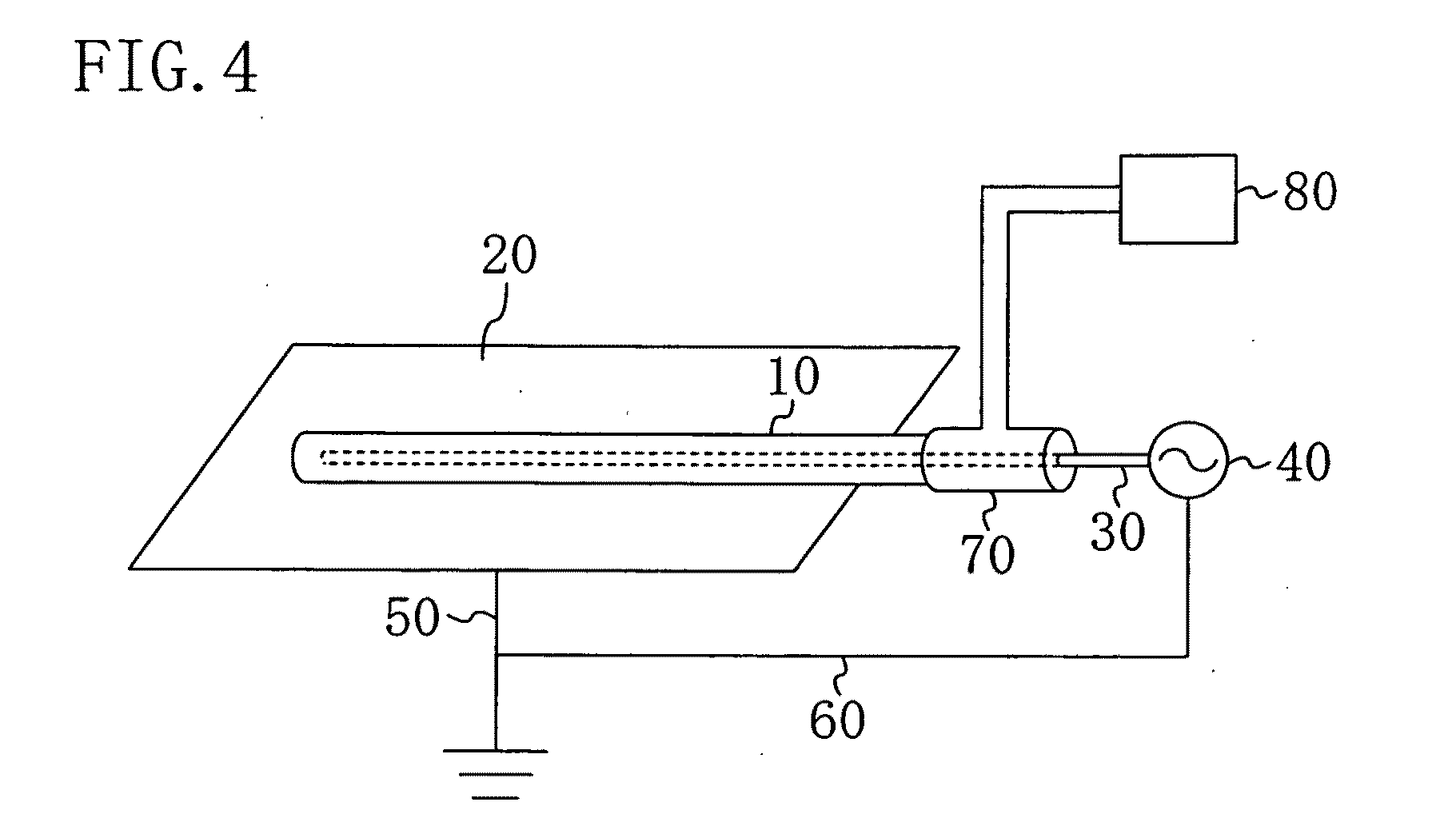
[0059]A plasma generation system of embodiment 2 includes, as shown in FIG. 4, a gas supplier 80 in addition to the components of the plasma generation system of embodiment 1. The plasma generation system and plasma generation method of embodiment 2 are substantially the same as those of embodiment 1, and the differences of embodiment 2 from embodiment 1 are mainly described below.
[0060]In this embodiment, an opening of the narrow tube 10 through which the first electrode 30 is to be inserted is provided with an adapter 70 which allows introduction of a predetermined gas from the gas supplier 80 into the cavity of the narrow tube 10. The adapter 70 and the gas supplier 80 are connected to each other by a pipe. An example of the gas supplier 80 is a compressed gas chamber with a pressure reduction valve. The predetermined gas refers to a gas selected from among a variety of gasses in view of the purpose of generation of plasma. For example, introduction of Ar or He into the cavity of...
example 1
[0068]The first electrode formed by a copper wire having a diameter of 0.254 mm and a Teflon® clad was inserted into the cavity of a PVC narrow tube having an outside diameter of 5 mm, inside diameter of 3 mm and length of 1 m, and an alternating voltage was applied to the first electrode to sterilize the inside of the narrow tube. Both ends of the narrow tube were sealed. The power supply used was an AC power supply of a sine wave at 6 kHz. Herein, the magnitude of the voltage applied is a peak-to-peak representation.
[0069]Results of plasma irradiation with varying voltage magnitudes and treatment durations (voltage application times) are shown in FIG. 5. Determination as to whether sterilization was successful or not was carried out using ATTEST290 and 290G available from 3M Company. The numbers shown with the upper and lower tables of FIG. 5, No. 1291 and No. 1294, refer to the numbers of the bioindicators used for the determination. The determination as to whether sterilization ...
PUM
 Abstract
Description
Claims
Application Information
 - R&D Engineer
- R&D Manager
- IP Professional
- Industry Leading Data Capabilities
- Powerful AI technology
- Patent DNA Extraction
Browse by: Latest US Patents, China's latest patents, Technical Efficacy Thesaurus, Application Domain, Technology Topic.
© 2024 PatSnap. All rights reserved.Legal|Privacy policy|Modern Slavery Act Transparency Statement|Sitemap