Ion trap mass spectromter

a mass spectrometer and ion trap technology, applied in mass spectrometers, separation processes, stability-of-path spectrometers, etc., can solve the problems of increasing analysis cost, reducing analysis throughput, and elongating the measurement time to obtain a measurement result, so as to improve analysis throughput, the effect of reducing the measurement time required for the creation of a mass spectrum with a comparable s/n and increasing signal intensity

Active Publication Date: 2010-03-18
SHIMADZU CORP
View PDF6 Cites 22 Cited by
  • Summary
  • Abstract
  • Description
  • Claims
  • Application Information

AI Technical Summary

Benefits of technology

[0045]In the ion trap mass spectrometer according to the present invention, while ions are captured in the ion trap, ions newly generated can further be added and injected into the ion trap. Therefore, the mass separation and detection can be performed after increasing the amount of the ions captured in the ion trap, and the target ion can be detected with higher signal intensity than before. Hence, a mass spectrum with a sufficiently high S / N can be created without repeating the mass analysis and summing up the results, or with less number of repetitions of such mass analysis and summing up. In addition, the measuring time required for the creation of a mass spectrum with a comparable S / N can be significantly reduced than ever before. Hence, the throughput of an analysis can be improved, and simultaneously the cost required for an analysis of one sample can be reduced.
[0046]As previously described, ions having different masses reach the ion inlet at different times even though they simultaneously depart from the ion source. Therefore, if the width of time during which ions can enter the ion trap is short, the range of mass of ions that can be injected becomes narrow. On the other hand, in the ion trap mass spectrometer according to the present invention, the time width during which ions can enter can be made relatively large. For example, according to the simulation computation performed by the inventors of the present patent application, which will be described later, even if this time width is set to as large as approximately 30 [μs], the amount of already captured ions hardly decreases. The time width of 30 [μs] is equivalent to fifteen cycles of the AC voltage at frequency 500 [kHz]. This is a considerably large period, and is effective to additionally inject ions of sufficiently large mass range into the ion trap.
[0047]In the embodiment in which the ion trap mass spectrometer according to the present invention is used for a mass calibration, the mass accuracy as high as an internal reference method can be achieved, while the troublesome sample preparation work and the problems in an ion generation associated with a general internal reference method are avoided. In addition, a mass calibration substantially as accurate as the internal reference method can be performed not only in a general mass analysis, but also in an MS / MS analysis or MSn analysis.

Problems solved by technology

However, this causes a problem in that the measuring time to obtain a measurement result, i.e. a final mass spectrum, is elongated.
Therefore, about 11 seconds are required for a total of ten times, and about 33 seconds for a total of thirty times. Accordingly, the throughput of analysis decreases and the cost of analysis increases.

Method used


Image

  • Ion trap mass spectromter
  • Ion trap mass spectromter
  • Ion trap mass spectromter

Examples


embodiments

First Embodiment

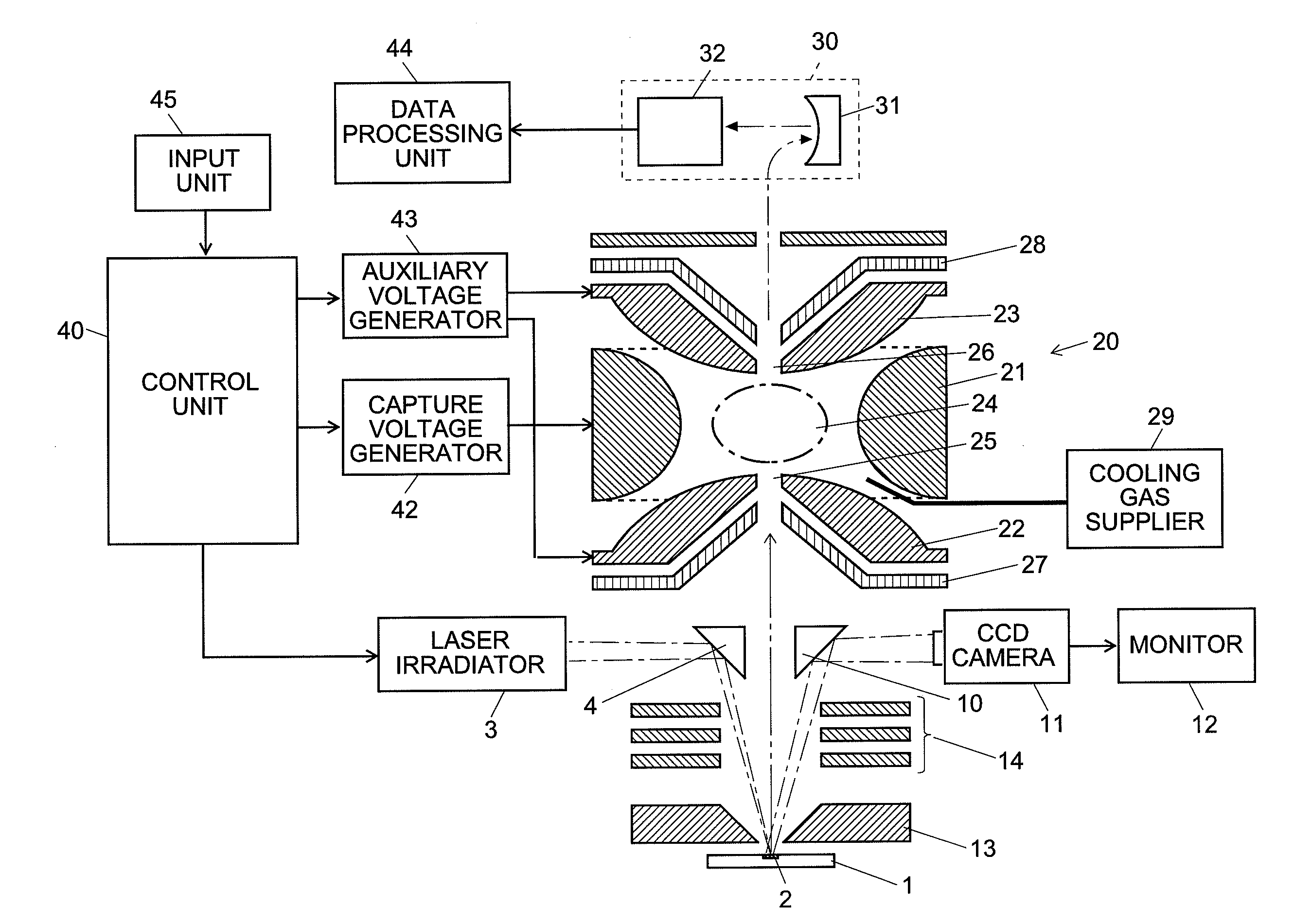
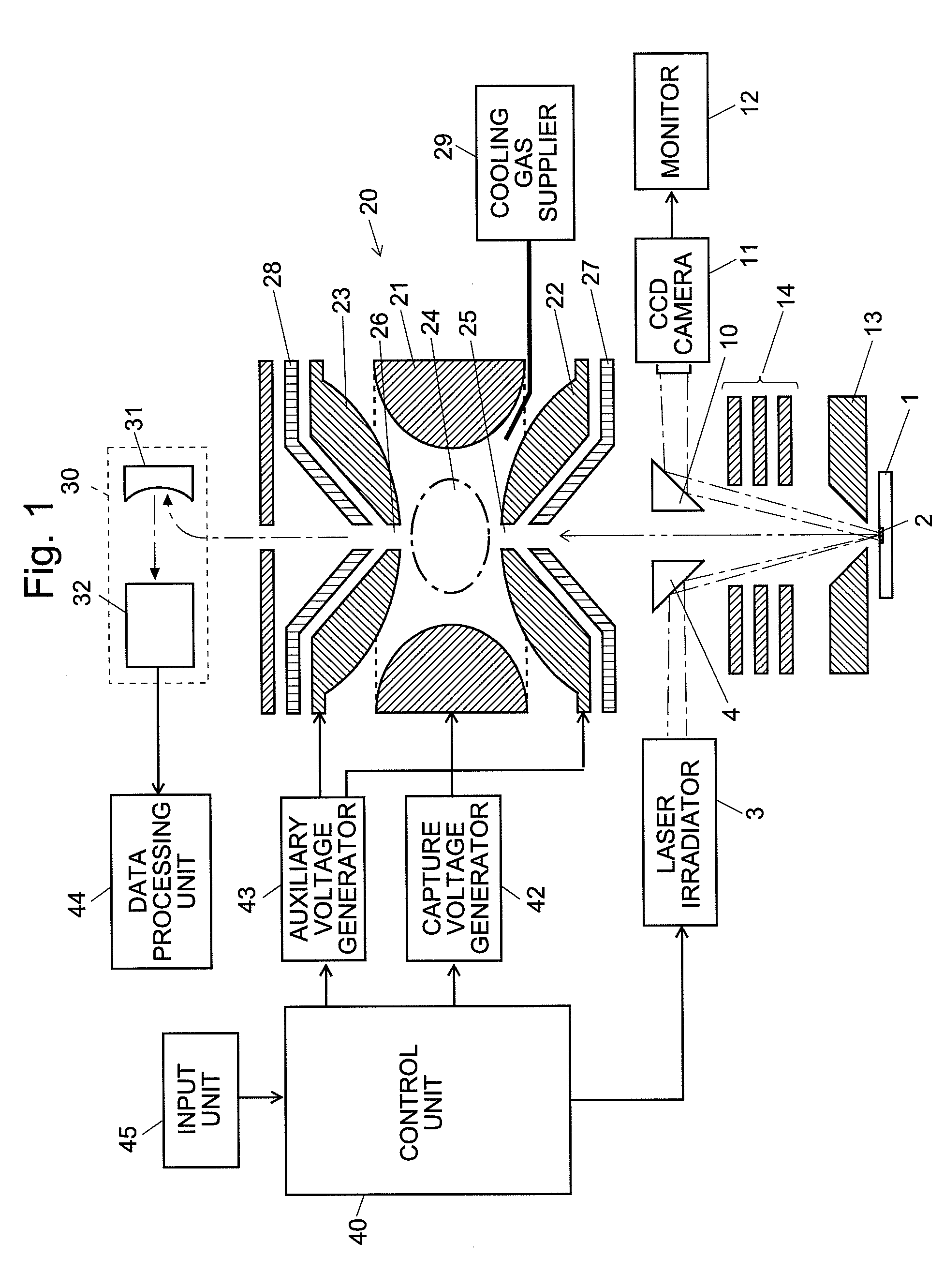
[0097]The configuration and operation of the matrix assisted laser desorption ionization digital ion trap mass spectrometer (MALDI-DIT-MS) which is an embodiment (the first embodiment) of the present invention will be described in detail. FIG. 1 is an entire configuration diagram of the MALDI-DIT-MS according to this embodiment.

[0098]The ion trap 20 is the previously-described three-dimensional quadrupole ion trap which is composed of a circular ring electrode 21 and a pair of end cap electrodes 22 and 23 opposing (high and low in FIG. 1) each other with the ring electrode 21 therebetween. An ion inlet 25 is bored through the substantially center of an entrance-side end cap electrode 22. Outside of the ion inlet 25, an entrance-side electric field correction electrode 27 is placed for correcting the disorder of the electric field around the ion inlet 25. At substantially center of the exit-side end cap electrode 23, an ion outlet 26 is bored substantially in alignmen...

second embodiment

[0126]Next, as another embodiment (the second embodiment) of the present invention, a MALDI-DIT-MS, in which the function of the additional ion injection into the ion trap as previously described is used for a mass calibration, will be described. Generally, in order to obtain data with high mass accuracy in a mass spectrometer, it is inevitable to perform a mass calibration using a standard sample whose mass-to-charge ratio is known. A mass calibration in a conventional MALDI-IT-MS is performed in the same manner as an apparatus without an ion trap such as a MALDI-TOFMS. Generally, there are two methods for performing a mass calibration in a MALDI-TOFMS: the external standard method and the internal standard method.

[0127]In performing a mass calibration by the external standard method, before a measurement of an analysis sample (analyte), an analysis operator applies a calibration sample (calibrant) including a compound whose mass-to-charge ratio is known at a different position on ...


PUM


Abstract

While applying a square wave voltage to the ion electrode (21) so that ions already captured in the ion trap (20) do not disperse, the frequency of the square wave voltage is temporarily increased at the timing when the ions generated in response to the short time irradiation of a laser light reach the ion inlet (25). This decreases the Mathieu parameter qz, and the potential well becomes shallow, which makes it easy for ions to enter the ion trap (20). Although the ions that have been already captured become more likely to disperse, the frequency of the square wave voltage is decreased before they deviate from the stable orbit. Thus, the dispersion of the ions can also be avoided. Accordingly, while the number of captured ions is not decreased, new ions are further added, and thereby the amount of ions can be increased. By performing a mass separation and detection after that, the signal intensity in one mass analysis can be increased. Thereby, the number of repetition of the mass analysis for summing up the mass profiles can be decreased, and the signal intensity can be increased while decreasing the measuring time.

Description

TECHNICAL FIELD[0001]The present invention pertains to an ion trap mass spectrometer having an ion trap for trapping ions by an electric field.BACKGROUND ART[0002]One conventionally known type of mass spectrometer uses an ion trap for capturing (or trapping) ions by an electric field. A typical ion trap is a so-called three-dimensional quadrupole ion trap, which has a substantially-circular ring electrode and a pair of end cap electrodes placed to face each other across the ring electrode. In such an ion trap, conventionally, a sinusoidal radio-frequency voltage is applied to the ring electrode to form a capture electric field, and ions are oscillated and trapped by this capture electric field. In recent years, the digital ion trap (DIT) for trapping ions by applying a square wave voltage in place of a sinusoidal voltage has been developed (refer to Non-Patent Document 1 and other documents).[0003]In the case where the sample is biological, a laser desorption ionization (LDI) source...

Claims


Application Information

Patent Timeline
Patent Type & Authority Applications(United States)
IPC IPC(8): H01J49/42
CPCH01J49/164H01J49/4295H01J49/424
Inventor IWAMOTO, SHINICHIKODERA, KEI
Owner SHIMADZU CORP
Why Eureka
Try Eureka