Display device
a technology of display device and display screen, which is applied in the direction of semiconductor devices, instruments, electrical apparatus, etc., can solve the problems that the transistor is not always suitable for a larger glass substrate, and achieve the effects of enhancing the function of the protective circuit, facilitating the operation, and facilitating the operation
- Summary
- Abstract
- Description
- Claims
- Application Information
AI Technical Summary
Benefits of technology
Problems solved by technology
Method used
Image
Examples
embodiment 1
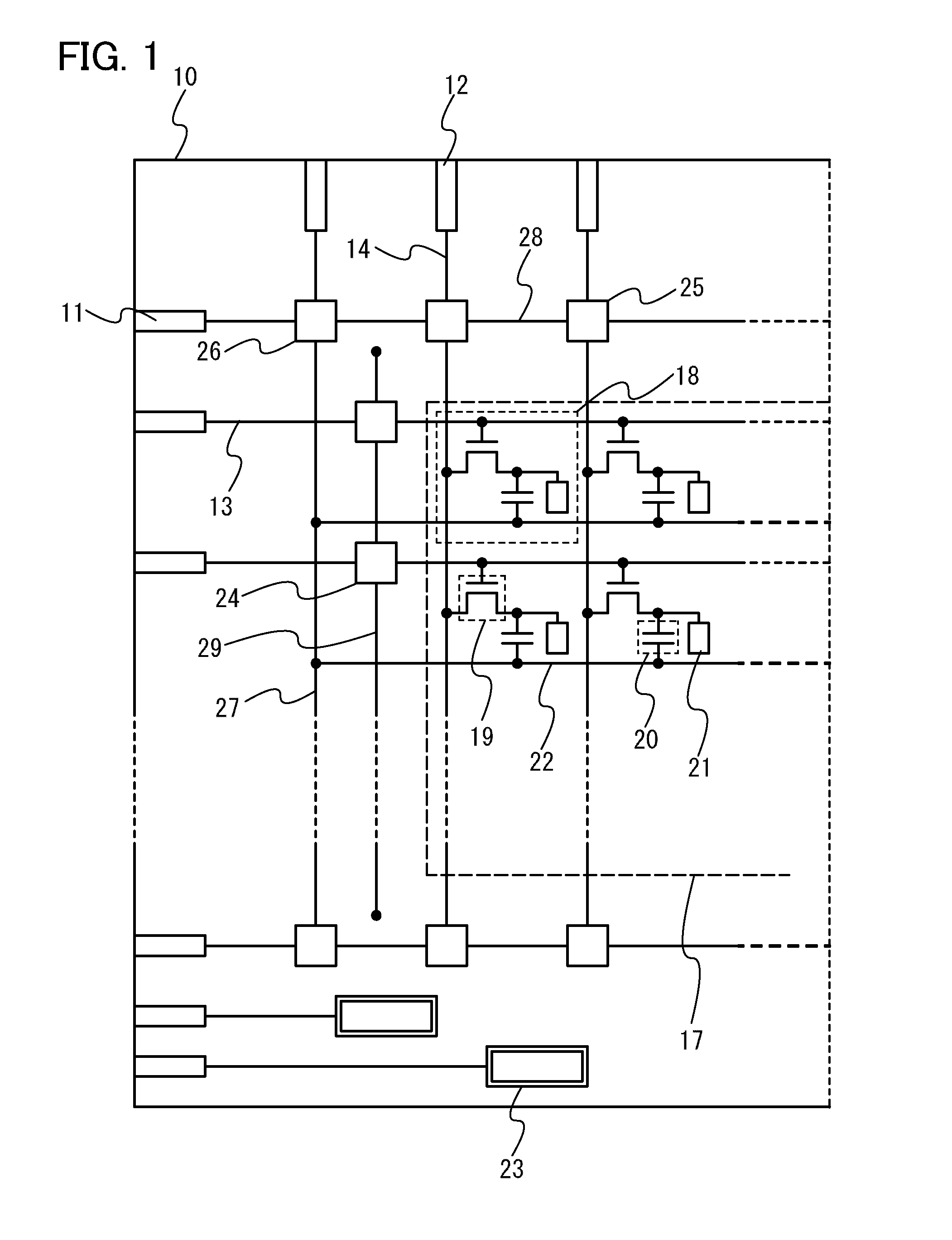
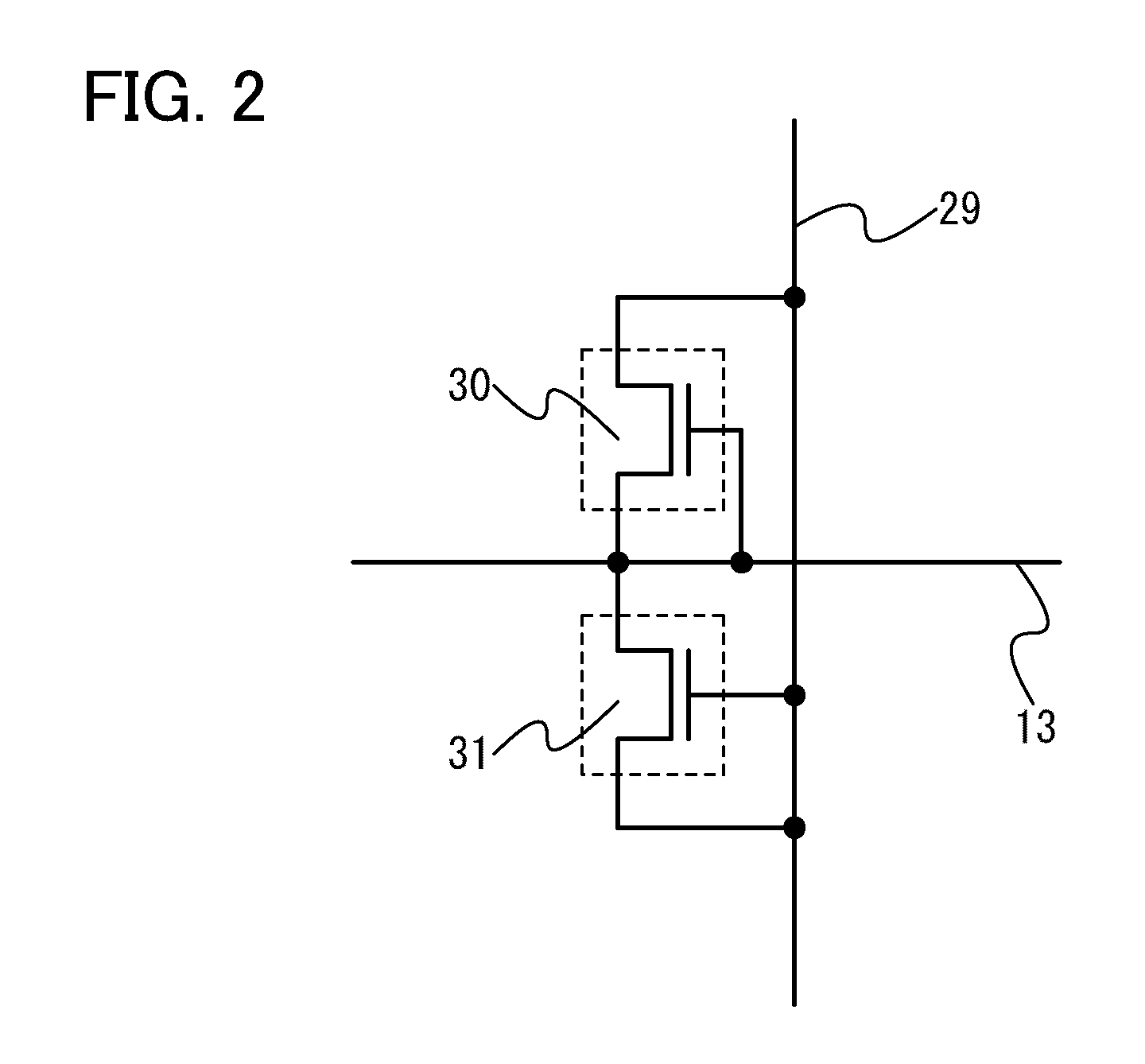
[0043]In Embodiment 1, an example of a display device including a pixel portion and a protective circuit including a non-linear element provided around the pixel portion is described with reference to drawings.
[0044]FIG. 1 illustrates a positional relationship between a pixel portion and protective circuits including signal input terminals, scan lines, signal lines, and non-linear elements in a display device. Over a substrate 10 having an insulating surface, scan lines 13 and signal lines 14 intersect with each other to form a pixel portion 17.
[0045]The pixel portion 17 includes a plurality of pixels18 arranged in matrix. The pixel 18 includes a pixel transistor 19 connected to the scan line 13 and the signal line 14, a storage capacitor portion 20, and a pixel electrode 21.
[0046]In the pixel structure illustrated here, one electrode of the storage capacitor portion 20 is connected to the pixel transistor 19 and the other electrode is connected to a capacitor line 22. Moreover, the...
embodiment 2
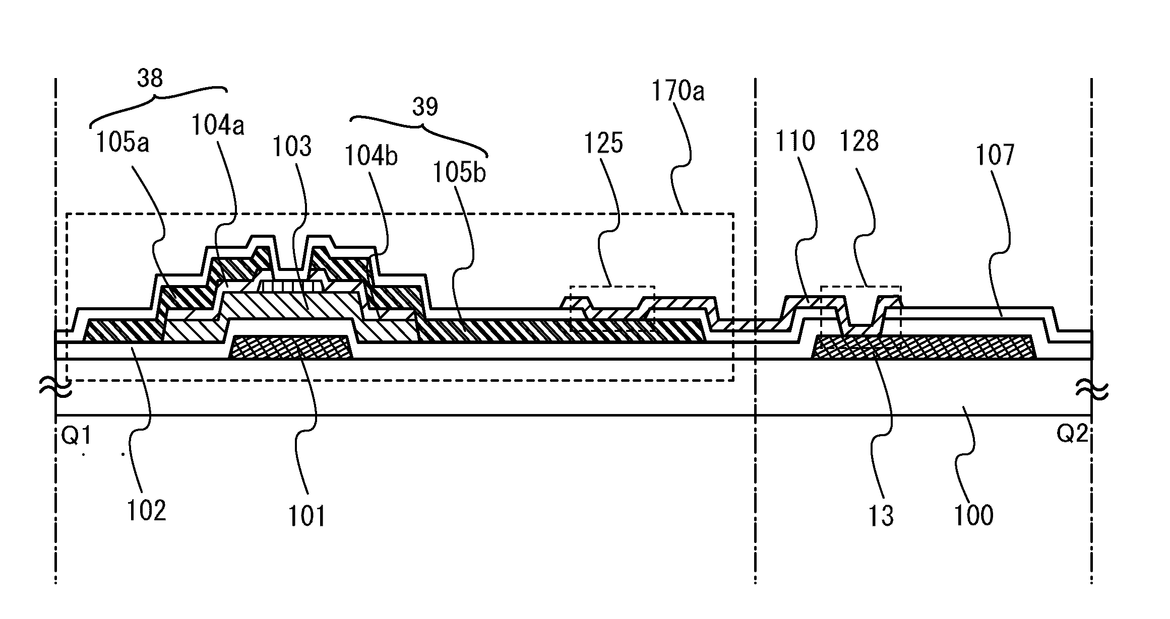
[0067]In Embodiment 2, one embodiment of a process for manufacturing a protective circuit illustrated in FIG. 4A in Embodiment 1 is described with reference to FIGS. 8A to 8C and FIGS. 9A to 9C. FIGS. 8A to 8C and FIGS. 9A to 9C are cross-sectional views taken along line Q1-Q2 of FIG. 4A.
[0068]In FIG. 8A, a glass substrate of barium borosilicate glass, aluminoborosilicate glass, aluminosilicate glass, or the like available in the market can be used as the substrate 100 having a light-transmitting property. For example, a glass substrate which includes more barium oxide (BaO) than boric acid (B2O3) in composition ratio and whose strain point is 730° C. or higher is preferable. This is because the glass substrate is not strained even when the oxide semiconductor layer is thermally processed at high temperatures of about 700° C.
[0069]Next, a conductive layer is formed entirely over the substrate 100. After that, a resist mask is formed by a first photolithography process, and an unnece...
embodiment 3
[0101]In Embodiment 3, an example of a display device including a pixel portion and a protective circuit including a non-linear element provided around the pixel portion, which is different from that of Embodiment 2, will now be described with reference to FIGS. 27A and 27B.
[0102]FIG. 27A is a cross-sectional view of a display device in which a thin film transistor arranged in a pixel portion and a protective circuit including a non-linear element are formed over the same substrate. In a non-linear element 270a, conductive layers (105a and 105b) serving as a source electrode and a drain electrode are provided in contact with the first oxide semiconductor layer 103.
[0103]In the non-linear element 270a, the conductive layer 105a and the conductive layer 105b are preferably in contact with the first oxide semiconductor layer 103 which is modified by plasma treatment. In Embodiment 3, the first oxide semiconductor layer 103 is subjected to plasma treatment before formation of the conduc...
PUM
 Abstract
Description
Claims
Application Information
 - R&D
- Intellectual Property
- Life Sciences
- Materials
- Tech Scout
- Unparalleled Data Quality
- Higher Quality Content
- 60% Fewer Hallucinations
Browse by: Latest US Patents, China's latest patents, Technical Efficacy Thesaurus, Application Domain, Technology Topic, Popular Technical Reports.
© 2025 PatSnap. All rights reserved.Legal|Privacy policy|Modern Slavery Act Transparency Statement|Sitemap|About US| Contact US: help@patsnap.com


