Energy efficient range

Inactive Publication Date: 2010-04-08
ENERON
View PDF66 Cites 22 Cited by
  • Summary
  • Abstract
  • Description
  • Claims
  • Application Information

AI Technical Summary

Benefits of technology

[0010]Further, a manufacturing process is disclosed that can produce the cookware with a high density of heat exchange channels cost effectively while using materials with a good thermal conductivity. Such cookware can also be manufactured in stainless steel in accordance with a manufacturing process to produce stainless steel cookware with linear heat exchange channels on the bottom.
[0011]Also disclosed is a metal plate that has heat exchange features that can

Problems solved by technology

Heat transfer from combustion sources can be inefficient.
This means a lot of energy is wasted during the cooking process.
As a result, people pay unnecessarily high energy bills and pro

Method used


Image

  • Energy efficient range
  • Energy efficient range
  • Energy efficient range

Examples


Embodiment Construction

[0029]Although the following detailed description contains many specifics for the purpose of illustration, anyone of ordinary skill in the art will readily appreciate that many variations and alterations to the following exemplary details may be made.

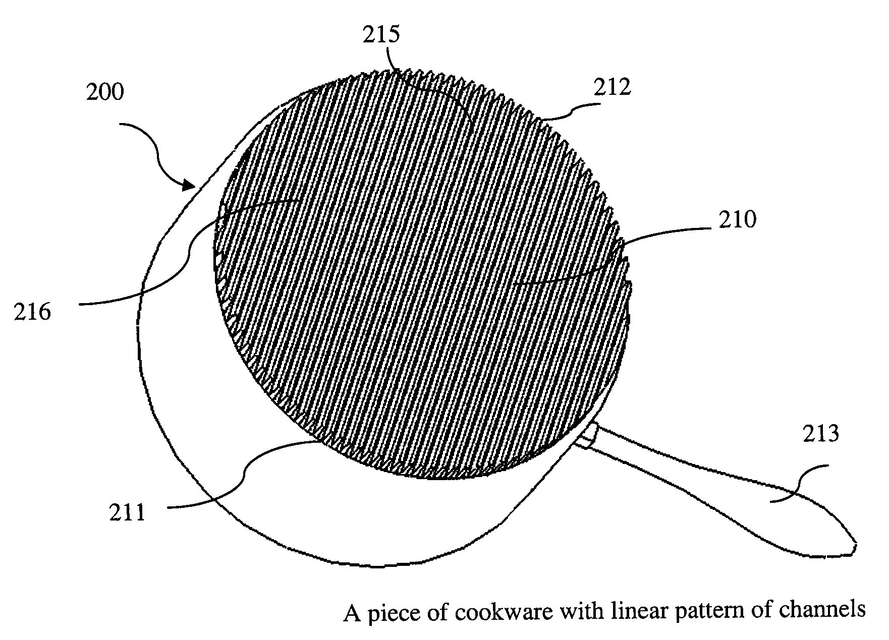
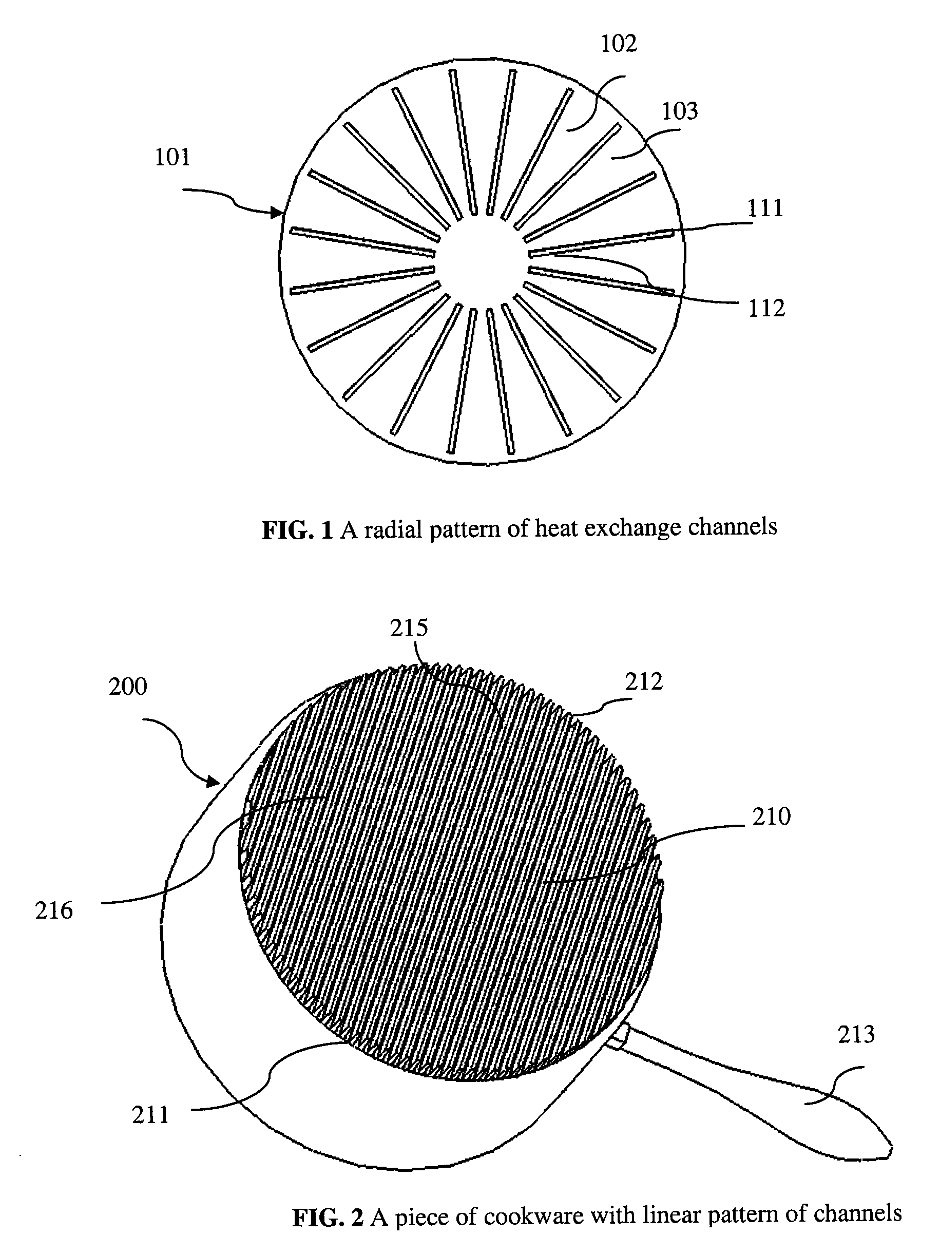
[0030]In a typical process, a piece of cookware holding a medium such as water is placed on top of a flame from a burner. The flame rises up due to pressure of the gas in the supply piping and the buoyancy of the hot air causes the flame to touch the base of the cookware. Heat is transferred from the flame to the base via convection transfer as well as radiation transfer. The heat is absorbed from the heat-receiving surface and is transferred to the food surface by thermal conduction. Heat is then transferred from the food surface to the water via conduction and convection. In this whole process, the heat transfer from the flame to the cookware body via convection transfer is the most inefficient step limited by the thick boundary layer...


PUM

PropertyMeasurementUnit
Mechanical strengthaaaaaaaaaa
Pressureaaaaaaaaaa
Areaaaaaaaaaaa

Abstract

Techniques for designing and creating energy efficient cookware are provided. In accordance with the techniques cookware can include a base and a wall and a linear pattern of flame guide channels connected to the base bottom. The guide channels accept flames and guide them to the perimeter from the central region resulting in efficient heat exchange. The linear channel profiles provides significant surface area enhancement from a given area on the bottom to improve heat transfer while providing even heating and mechanical strength to the cookware. A flame entrance opening is provided in the center region of the base to allow easy entrance of the flame into the channels. A gas burner flame pattern is provided to work with the linear channels profiles of the cookware to further improve the energy efficiency. A method of making the efficient cookware is provided involving deep drawing an extruded fin plate; A method of making the efficient cookware is provided involving spin cutting and spin forming of an extruded plate. A plate with heat exchange features that can be used either as the base of a piece of cookware or attached to the base of a piece of cookware can improve efficiency of heat transfer to the cookware.

Description

FIELD OF THE INVENTION[0001]The invention relates generally to cookware. More particularly, the invention relates to heat transfer from a heating element to cookware, especially from a flame over a gas range during a cooking process.BACKGROUND[0002]Cookware is a basic tool used daily in human life. Regardless of different shapes of cookware, ranging from a stock pot to a wok, to a frying pan, cookware can include two basic elements: one for receiving heat from a heat source, and one for heating food. Heat energy can be generated from a variety of sources, for example electricity, or a burning flame. The heat energy is transferred from the source to the heat-receiving surface of the cookware, conducted through the cookware and transferred to food in the cookware.[0003]Heat transfer from combustion sources can be inefficient. The utilization of thermal energy from gas on a typical gas range for heating up cookware is reported to be only about 30%. This means a lot of energy is wasted ...

Claims


Application Information

Patent Timeline
IPC IPC(8): A47J27/00A47J36/00
CPCY10T29/4935A47J27/022
Inventor HUANG, LEE LISHENG
Owner ENERON
Why Eureka
Try Eureka