
Liquid crystal molecule, liquid crystal display device and liquid crystal optical spatial modulation device

a liquid crystal molecule and optical spatial modulation technology, applied in the direction of organic chemistry, thin material processing, silicon organic compounds, etc., can solve the problems of low low frame rate drive, and inability to radically solve the foregoing problems, etc., to achieve excellent dynamic image display quality, large tilt angle, and high gradation properties and contrast. high

Inactive Publication Date: 2010-04-08
SONY CORP
View PDF7 Cites 1 Cited by
  • Summary
  • Abstract
  • Description
  • Claims
  • Application Information

AI Technical Summary

Benefits of technology

The present invention provides a liquid crystal molecule with a large tilt angle in an electroclinic effect, which can achieve sufficient optical modulation for use in a liquid crystal display device and a liquid crystal optical spatial modulation device. The liquid crystal molecule has a structure represented by a general formula and includes a compound with an asymmetric carbon atom and a core portion containing a naphthylene group and an organosiloxane or organosilane group. The invention also provides a liquid crystal display device and a liquid crystal optical spatial modulation device using the liquid crystal molecule. The liquid crystal molecule has a large tilt angle in an electroclinic effect, which allows for sufficient optical modulation and can be used in high-speed optical spatial modulation devices. The invention also provides a method for regulating the transmittance of the liquid crystal layer through the inclination of the longitudinal axis of the liquid crystal molecules through the impression of an electric field on the liquid crystal layer from the electrodes.

Problems solved by technology

However, it is the actual situation that the LCD is inferior to a plasma display (PDP), a field emission display (FED) and the like in display quality regarding dynamic images due to, for example, dynamic image blur to be caused by a slow response speed of a liquid crystal material itself.
Namely, the foregoing problem may not radically be solved, and the high frame rate drive may not be realized, unless the liquid crystal material is responsible to a high speed.
However, the tilt angle which has hitherto been revealed in liquid crystal materials is not so large that sufficient optical modulation is not obtainable yet.
Thus, such a liquid crystal material is still insufficient in consideration of putting a display device or the like into practical use.
However, this liquid crystal molecule is not sufficiently satisfactory in view of the fact that a tilt angle is small, and a more increase of the tilt angle is desirable.

Method used


Image

  • Liquid crystal molecule, liquid crystal display device and liquid crystal optical spatial modulation device
  • Liquid crystal molecule, liquid crystal display device and liquid crystal optical spatial modulation device
  • Liquid crystal molecule, liquid crystal display device and liquid crystal optical spatial modulation device

Examples


example 1

6-{[(R)-1-Methyl-5-(1,1,3,3,3-pentamethyldisiloxanyl)hexyl]-oxy}-5-nitronaphthyl-2-yl 4-(dodecyloxy)benzoate

(1) Synthesis of Liquid Crystal Molecule:

[0072]A liquid crystal molecule of an embodiment according to the present invention was obtained by the following procedures.

[0073]After adding dropwise benzoyl chloride to a pyridine solution of 2,6-naphthol, the mixture was stirred at room temperature overnight, and the thus obtained deposit was filtered and subjected to column chromatography with a silica gel to obtain 6-hydroxy-2-naphthyl benzoate.

[0074]The thus obtained 6-hydroxy-2-naphthyl benzoate was dispersed in acetic acid, nitric acid was added dropwise to the dispersion while keeping it at 15° C., and water was further added thereto, followed by stirring. The thus obtained deposit was recrystallized from ethanol / acetic acid to obtain 6-hydroxy-5-nitro-2-naphthyl benzoate.

[0075]An argon-purged flask was charged with the thus obtained 6-hydroxy-5-nitro-2-naphthyl benzoate, tri...

example 2

6-{[(R)-1-Methyl-4-(1,1,3,3,3-pentamethyldisiloxanyl)heptyl]-oxy}-5-nitronaphthyl-2-yl 4-(dodecyloxy)benzoate

[0086]Synthesis was carried out in the same manner as in Example 1, except for using (S)-4-octen-2-ol in place of the (5)-5-hepten-2-ol, thereby obtaining 6-{[(R)-1-methyl-4-(1,1,3,3,3-pentamethyldisiloxanyl)heptyl]-oxy}-5-nitronaphthyl-2-yl 4-(dodecyloxy)benzoate (final product 2).

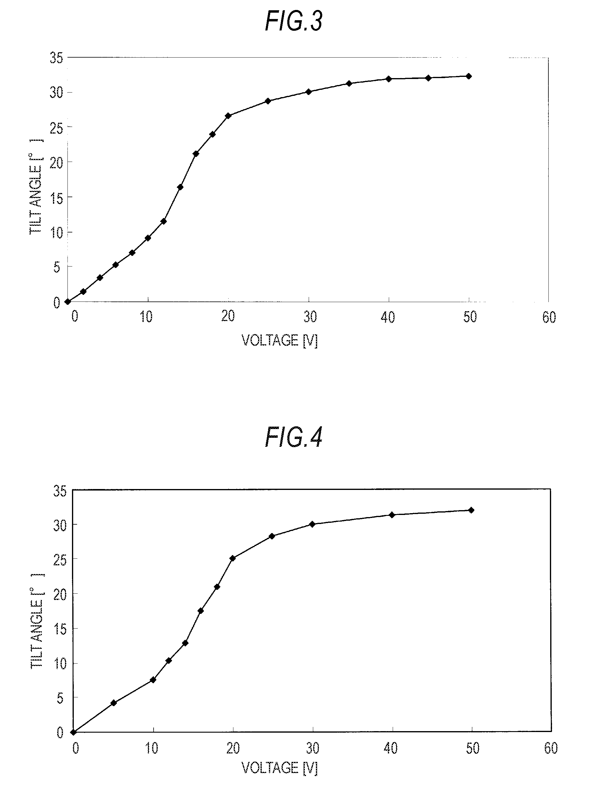
[0087]The final product 2 displayed a smectic A phase at from 32° C. to 52° C. The dependency of a tilt angle thereof on the impressed voltage is shown in FIG. 4.


PUM

PropertyMeasurementUnit
tilt angleaaaaaaaaaa
transmittanceaaaaaaaaaa

Abstract

A liquid crystal molecule is disclosed, having a structure represented by the following general formula (1):whereinX1 is a group selected among groups represented by the following formula (2):X2 is represented by the following formula (3):R1 represents a linear or branched hydrocarbon group or an alkoxy group each having from 4 to 16 carbon atoms;R2 represents an optionally branched organosiloxane or organosilane having from 1 to 6 silicon atoms;R3 and R4 are different from each other and each represents H, F, Cl, Br, CN, CH3, CF3 or OCH3;Y1 represents -, —COO—, —CH2—, —CH2O—, —C2H2—, —C2— or —CF2O—;Z1 to Z4 each represents H, F, Cl, Br, OH, NO2, CN, CF3, CH3, C2H5, OCH3 or OC2H5;Z5 to Z7 each represents H, F, Cl, Br, OH, NO2, CN or CF3, provided that Z5, Z6 and Z7 do not represent H at the same time;n represents an integer of from 1 to 6;* represents a chiral center; and- means a connecting group.

Description

BACKGROUND OF THE INVENTION[0001]1. Field of the Invention[0002]The present invention relates to a liquid crystal molecule and to a liquid crystal display device and a liquid crystal optical spatial modulation device each using the liquid crystal molecule.[0003]2. Description of the Related Art[0004]In recent years, a liquid crystal display device (LCD) of an active matrix driving type such as a TFT (thin film transistor) has been widely used over the range of from small mobile uses to large television sets.[0005]In the LCD, techniques such as impulse driving have been being adopted, thereby attempting to realize a high response speed. However, it is the actual situation that the LCD is inferior to a plasma display (PDP), a field emission display (FED) and the like in display quality regarding dynamic images due to, for example, dynamic image blur to be caused by a slow response speed of a liquid crystal material itself.[0006]Meanwhile, attempts have also been being made to increase...

Claims


Application Information

Patent Timeline
Patent Type & Authority Applications(United States)
IPC IPC(8): C09K19/02C07F7/10
CPCC07F7/0818Y10T428/10C09K19/406C07F7/081C09K2323/00
Inventor KOTAKE, RIKATAKANASHI, HIDEHIKOKOBAYASHI, KEN
Owner SONY CORP
Learn More