Configurations and Methods for Ambient Air Vaporizers

a technology configuration method, which is applied in the direction of fluid transfer, container discharging method, gas handling/storage effect, etc., can solve the problems of uneconomical or even impractical, the footprint of ambient air vaporizers for regasification of lng is rather large, and the vaporization duty of currently known ambient air vaporizers is small, so as to achieve the effect of reducing energy consumption

Inactive Publication Date: 2010-04-29
FLUOR TECH CORP
View PDF15 Cites 9 Cited by
  • Summary
  • Abstract
  • Description
  • Claims
  • Application Information

AI Technical Summary

Benefits of technology

[0009]The present invention is directed to various configurations and methods of vaporizing a cryogenic fluid in an ambient air vaporizer in which water is condensed from the ambient air using refrigeration content of partially heated cryogenic fluid to so form dehydrated air that is then employed to heat the cryogenic fluid, thereby producing the partially heated cryogenic fluid. Consequently, continuous operation without need for defrosting cycles and / or defrosting fluid is possible at reduced energy consumption.
[0012]Most preferably, the first section comprises a coalescing filter or element and a drain fluidly coupled to the collection tray, and the first and second sections are vertically coupled to each other to allow top-to-bottom or downward air flow. It is also preferred that a fan is coupled to the enclosure and forces ambient air into the first section. While not limiting to the inventive subject matter, it is generally further preferred that a control system maintains the air temperature in the first section above 32° F., for example, by controlling flow of vaporized cryogenic fluid out of the first section and / or by controlling flow of the cryogenic fluid into the second section. Alternatively, or additionally, a control system is contemplated that reduces the feed rate of cryogenic fluid to the vaporizer allowing a controlled defrosting process using heat from the ambient air and the coalescer trays in the upper section, to so avoid the hazard associated with falling ice in conventional ambient air vaporizers.

Problems solved by technology

Unfortunately, the vaporization duty of currently known ambient air vaporizers is small when compared to the large duties required by LNG regasification terminals.
Therefore, most known ambient air vaporizers for regasification of LNG require a rather significant footprint, which is often uneconomical or even impractical, particularly in offshore and floating LNG regasification facilities.
While most of such ambient air exchangers regasify LNG relatively efficiently during at least some period of operation, ice formation and accumulation on the outer fins, especially in the lower part of the exchangers where the LNG enters; impedes heat transfer due to the insulating property of ice.
Moreover, ice layers may be unevenly distributed along the tubes, adding weight to the exchangers, and potentially even changing the center of gravity of the exchanger.
Excessive ice layer formation is also problematic in the structural design to meet stringent structural code requirements for wind and seismic loads.
In many cases, de-icing is done by natural draft convection, which is time consuming.
However, such operation is rarely effective due to additional ice formation that further inhibits the heating operation, while requiring high energy consumption of the air circulation fans (e.g., in hot and humid environment, over 50% of the operational cost for heat exchangers is due to de-icing or defrosting requirements).
Operation of most known ambient air vaporizers is also subject to environmental factors such as temperature, relative humidity, wind, solar radiation, and / or surrounding structures.
Even circadian variations in humidity and dry bulb temperature may affect the heat exchanger performance.
Despite some advantages obtained in such devices and methods, pumping, heating, and temperature regulation of the intermediate heat transfer fluid requires considerable energy and adds to the complexity and space requirements of the LNG vaporizers.
Therefore, while numerous configurations and methods of ambient air vaporization of LNG are known in the art, all or almost all of them suffer from one or more disadvantages.

Method used


Image

  • Configurations and Methods for Ambient Air Vaporizers
  • Configurations and Methods for Ambient Air Vaporizers
  • Configurations and Methods for Ambient Air Vaporizers

Examples


Embodiment Construction

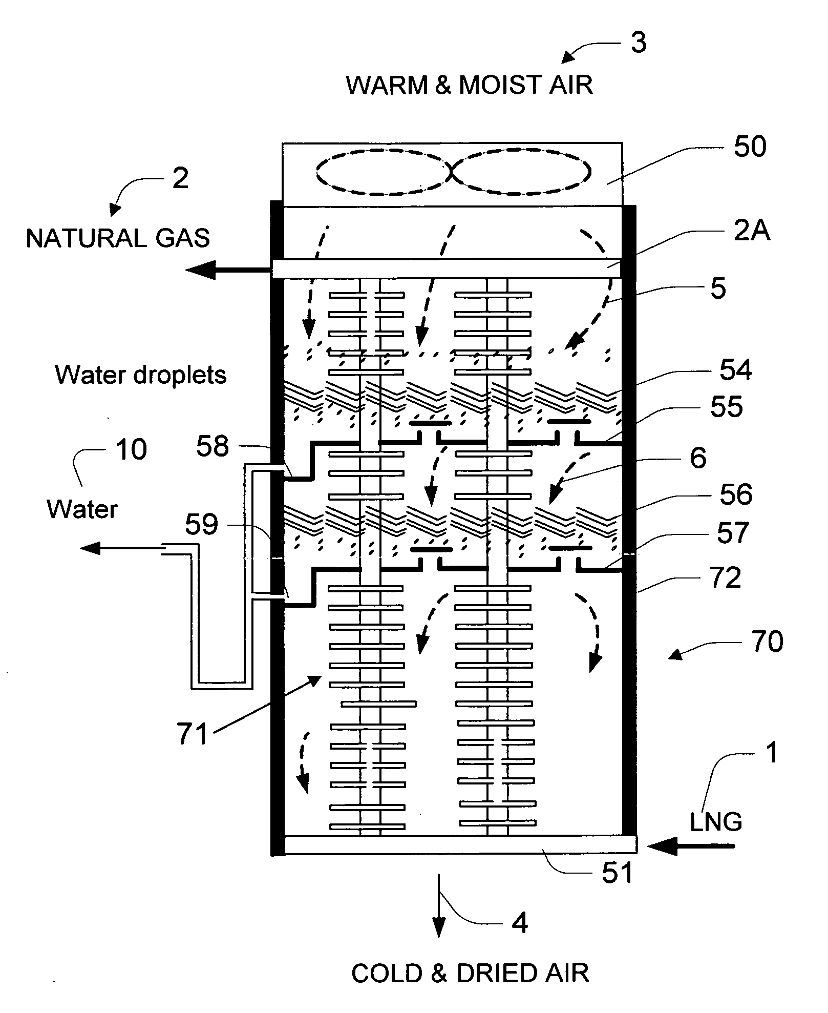
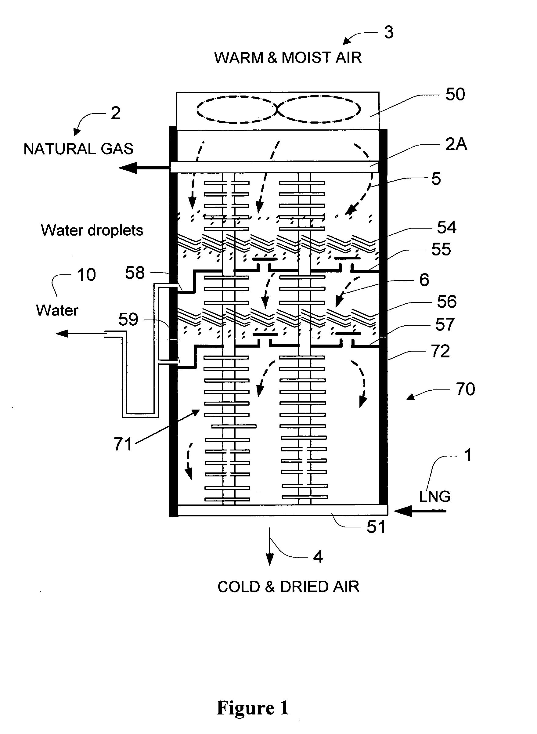
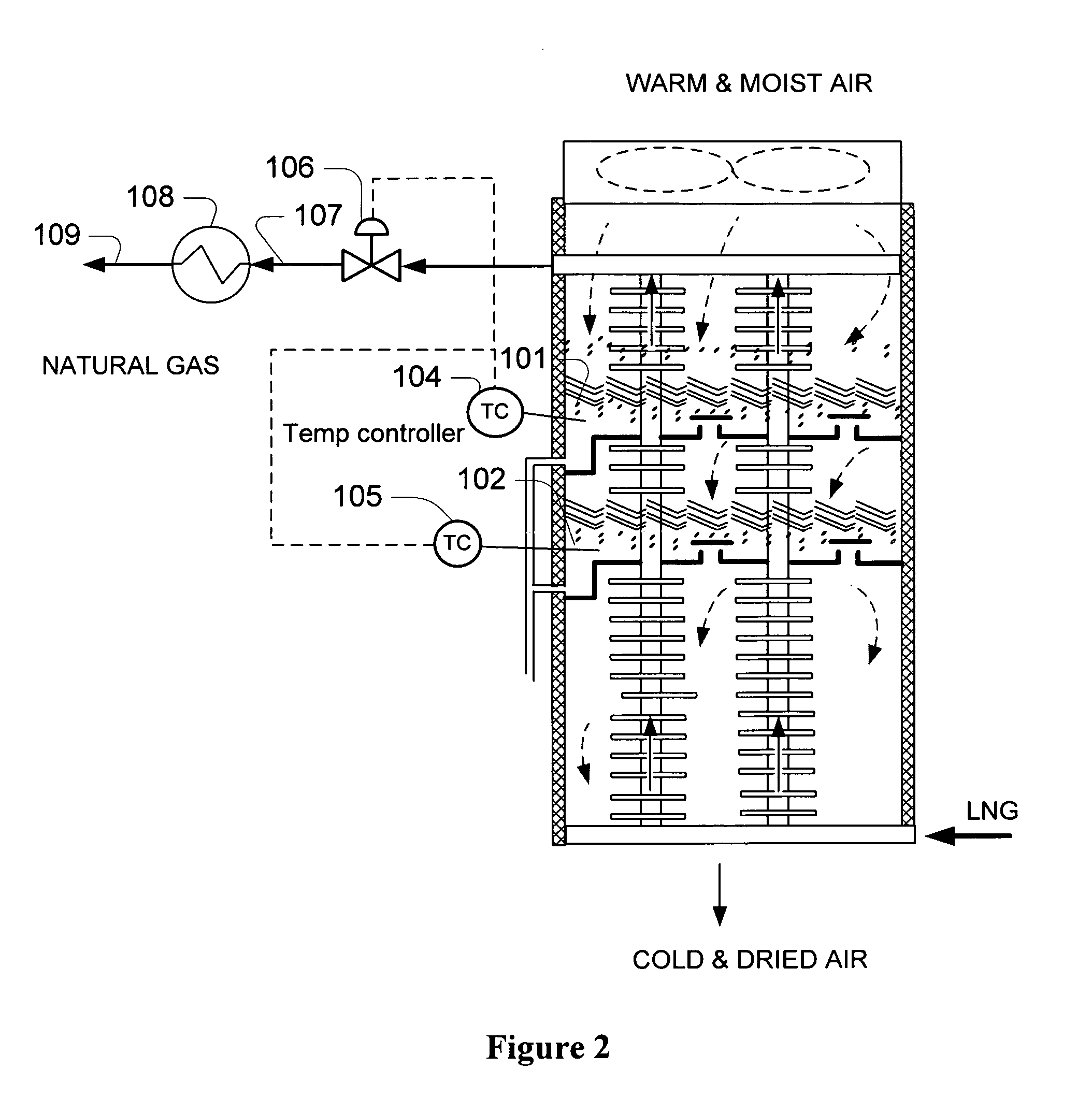
[0020]The inventor has discovered that defrosting of ambient air vaporizers can be reduced or even be entirely avoided in devices and methods in which water is condensed and removed from ambient air in a section of the vaporizer that operates at a temperature at about or above the freezing point of water and in which the so cooled and dried air is then further used for vaporization in another section of the exchanger. Most preferably, such sections are arranged in series and employ forced air flow, and the moisture is removed from the warm section of the vaporizer using various devices that may include a coalescence filter, separation device and condensate drain system. Most preferably, a control system is implemented that provides frost free operation under various ambient temperatures and relative humidities.

[0021]It should be appreciated that such configurations eliminate or reduce defrosting time, increase the on-stream operation, and reduce heat exchange size and plant footprin...


PUM


Abstract

Cryogenic fluid is vaporized using two sections of an ambient air vaporizer where in the first section ambient air is dehydrated at a temperature at or above freezing point of water using refrigeration content of partially heated cryogenic fluid, wherein the dehydrated air is used in the second section to form the partially heated cryogenic fluid from a cryogenic fluid.

Description

[0001]This application claims priority to our copending U.S. provisional applications having Ser. No. 60 / 940,066 (filed May 24, 2007) and Ser. No. 60 / 942,150 (filed Jun. 5, 2007).FIELD OF THE INVENTION[0002]The field of the invention is configurations and methods of vaporization of cryogenic gases, and especially liquefied natural gas (LNG) using ambient air as heat source.BACKGROUND OF THE INVENTION[0003]Atmospheric ambient air vaporizers are well known in the art and commonly used in many cryogenic liquid plants to vaporize various cryogenic liquids, and especially liquefied natural gas. Atmospheric vaporizers are typically based on heat exchanger configurations in which sensible heat of air and latent heat of water is used to heat a very low boiling cryogenic liquid (e.g., liquid oxygen, liquid nitrogen, or liquefied natural gas) to a temperature above the boiling point.[0004]Unfortunately, the vaporization duty of currently known ambient air vaporizers is small when compared to ...

Claims


Application Information

Patent Timeline
Patent Type & Authority Applications(United States)
IPC IPC(8): F17C9/02
CPCF17C9/02F17C2221/033F17C2223/0161F17C2223/033F17C2225/0123F17C2227/0313F17C2265/05F17C2227/0393F17C2227/0397F17C2250/0631F17C2260/032F17C2260/046F17C2227/0327
Inventor MAK, JOHN
Owner FLUOR TECH CORP
Why Eureka
Try Eureka