Fluid Assisted Gas Gauge Proximity Sensor

a gas gauge and proximity sensor technology, applied in the field of proximity sensors, can solve the problems of destroying the quality of the material surface or product being worked on, affecting the accuracy of the proximity sensor, and causing the proximity sensor to fail to meet the requirements of the application

Inactive Publication Date: 2010-04-29
ASML HLDG NV
View PDF17 Cites 9 Cited by
  • Summary
  • Abstract
  • Description
  • Claims
  • Application Information

AI Technical Summary

Benefits of technology

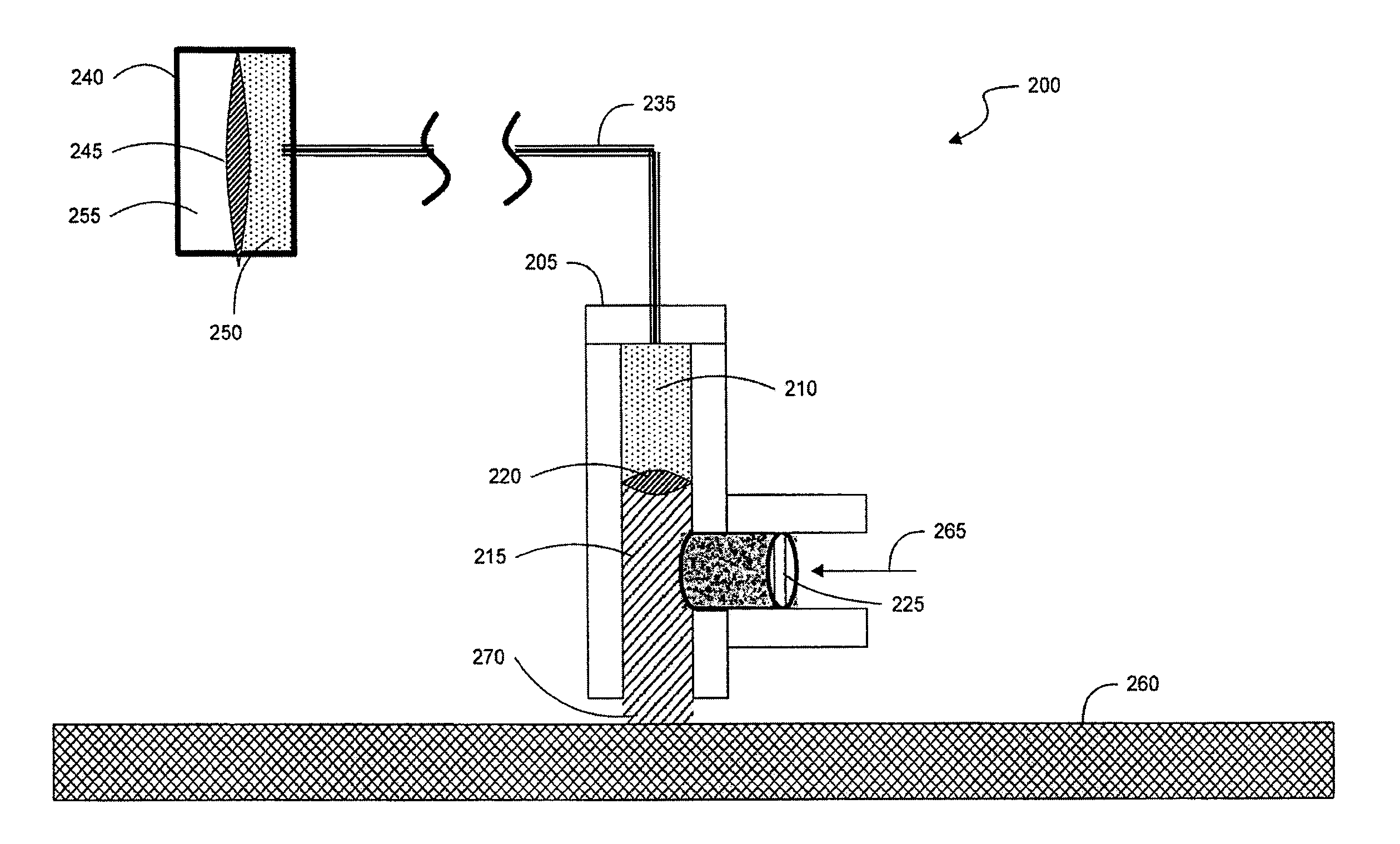
[0014]In a further embodiment of the present invention, a bridge version of the proximity sensor can be used. In this embodiment, two arms, a measurement arm and a reference arm, are used to provide a differential pressure measurement. Both arms have a measurement chamber and a transfer chamber, but the reference arm is provided with a reference standoff that is set a prescribed distance from the exit aperture of the reference measurement chamber. Both the measurement arm and the reference arm are supplied with gas from the same gas source. In this embodiment, the difference in pressure readings found in the measurement and reference arms is used to determine the separation (and therefore the topography) of the surface of the substrate from the proximity sensor. The bridge embodiment offers the advantage that any common mode errors (such as pressure variations within the gas source) are eliminated since they affect both sides of the bridge and are thereby cancelled in the differential measurement.

Problems solved by technology

The challenges associated with creating a proximity sensor of such accuracy are significant, particularly in the context of photolithography systems.
Occurrence of either situation may significantly degrade or ruin the quality of the material surface or product being worked upon.
These proximity sensors have serious shortcomings when used in lithographic projection systems because the physical properties of materials deposited on wafers may impact the precision of these sensors.
For example, capacitance gauges, being dependent on the dielectric of intervening layers, can yield spurious proximity readings in locations where a mix of material (e.g., metal) is concentrated.
More generally, optical and capacitive methods are prone to errors due to significant interactions with layers beneath photoresist coatings.
Another class of problem occurs when exotic wafers made of non-conductive and / or photosensitive materials, such as Gallium Arsenide (GaAs) and Indium Phosphide (InP), are used.
In these cases, capacitance gauges and optical gauges may provide spurious results, and are therefore not optimal.
However, gas gauge proximity sensors are limited in their response time by virtue of their internal cavity volumes.
Internal cavity volumes impose a finite time constant that limits the ability to shorten their available response time.
Although the time constant may be lessened by reducing the size of the internal cavity volume, there are practical limitations as to how small the internal cavity volume can become.
For example, the pressure sensing component of the proximity sensor often cannot be placed physically close to the nozzle of the proximity sensor.
Moreover, sensitivity requirements often dictate the need for large sensor sizes.
Further, the need for low pressures, such as those employed in extreme ultraviolet (EUV) based lithographic tools, exacerbates further the response time challenge.
Thus despite the benefits of these gas gauge types of proximity sensors, the specter of a severely limited bandwidth remains a crucial obstacle to the use of air gauge proximity sensors.

Method used


Image

  • Fluid Assisted Gas Gauge Proximity Sensor
  • Fluid Assisted Gas Gauge Proximity Sensor
  • Fluid Assisted Gas Gauge Proximity Sensor

Examples


Embodiment Construction

[0021]This specification discloses one or more embodiments that incorporate the features of this invention. The disclosed embodiment(s) merely exemplify the invention. The scope of the invention is not limited to the disclosed embodiment(s). The invention is defined by the claims appended hereto.

[0022]The embodiment(s) described, and references in the specification to “one embodiment”, “an embodiment”, “an example embodiment”, etc., indicate that the embodiment(s) described may include a particular feature, structure, or characteristic, but every embodiment may not necessarily include the particular feature, structure, or characteristic. Moreover, such phrases are not necessarily referring to the same embodiment. Further, when a particular feature, structure, or characteristic is described in connection with an embodiment, it is understood that it is within the knowledge of one skilled in the art to effect such feature, structure, or characteristic in connection with other embodimen...


PUM

PropertyMeasurementUnit
wavelengthaaaaaaaaaa

Abstract

A fluid assisted gas gauge coupled to a pressure sensor enables proximity measurements to be made with a high bandwidth. A two-chamber gas gauge, containing a gas-filled measurement chamber and a fluid-filled transfer chamber and a diaphragm separating the two chambers, exhausts gas onto the surface being measured, while the incompressible fluid transmits the pressure to a pressure sensor. By minimizing the gas volume of the gas gauge, the response time is enhanced. In addition, the incompressible fluid permits the pressure sensor to be remotely located from the point of measurement without sacrificing the response time performance. In an embodiment, a differential bridge version of the fluid assisted gas gauge reduces common mode effects.

Description

CROSS REFERENCE TO RELATED APPLICATION(S)[0001]This application claims benefit under 35 U.S.C. §119(e) to U.S. Provisional Patent Application No. 61 / 107,880, filed Oct. 23, 2008, which is incorporated by reference herein in its entirety.BACKGROUND[0002]1. Field of the Invention[0003]The present invention relates to a proximity sensor, and in particular to a proximity sensor for use in semiconductor lithographic applications.[0004]2. Related Art[0005]Many automated manufacturing processes require the sensing of the distance between a manufacturing tool and the product or material surface being worked upon. In some situations, such as semiconductor lithography, that distance must be measured with an accuracy approaching a nanometer.[0006]The challenges associated with creating a proximity sensor of such accuracy are significant, particularly in the context of photolithography systems. In the photolithography context, in addition to the needs to be non-intrusive and to precisely detect...

Claims


Application Information

Patent Timeline
Patent Type & Authority Applications(United States)
IPC IPC(8): G03B27/72G01L13/02
CPCG03B27/72G01B13/00G03F9/7057
Inventor LYONS, JOSEPH H.SCHULTZ, GEOFFREY ALAN
Owner ASML HLDG NV
Why Eureka
Try Eureka