
Substrate for lithium thin film battery

a thin film battery and substrate technology, applied in the field of lithium ionswitching devices, can solve the problems of reducing the capacity of the battery, preventing the use of a metal foil as such for batteries, and unable to use high temperature resistant polymers such as polyimides, so as to improve the retention of lithium in the device, prevent the loss of lithium, and improve the adhesion of the first electrode

Inactive Publication Date: 2010-04-29
CYMBET CORP
View PDF9 Cites 37 Cited by
  • Summary
  • Abstract
  • Description
  • Claims
  • Application Information

AI Technical Summary

Benefits of technology

[0022]It is an object of the invention to provide a thin film lithium ion switching devices on a metal substrate. The metal substrate is particularly suited to deposit such a device on. It is a further object of the invention to provide such a substrate without the need of depositing an additional layer to grow the first electrode on. Another object of the invention is to provide a metal foil that forms a lithium impermeable barrier so as to better retain the lithium in the device and to prevent loss of lithium to the substrate. In addition it is an object of the invention to provide such a substrate that also allows for sufficient electrical conduction thereby eliminating the need for an additional current collector. Furthermore, it is an object of the invention to provide a substrate material that gives good adhesion of the first electrode to the substrate and remains flexible at all times.
[0032]When now three elements are present in the alloy, the alloy element of the lowest electrochemical potential will first oxidise and form a layer on the substrate. The second metal may reduce the critical concentration needed for establishing a closed external oxide scale of the third alloy element (being a metal or silicon). The second metal prevents, by its own internal oxidation, the continued oxide diffusion into the alloy, so that the internal oxidation of the third alloy element is limited and the external oxidation of the third alloy element will prevail. However, due to the depletion of the upper layer of the third element and the blocking of the second metal oxide, the growth of the third alloy element oxide will be limited. In this manner, the degradation and continued growth of the third alloy element oxide can be limited and even controlled.
[0049]However, the idea of using these alloys is not limited to self supporting foils. Indeed, the alloy could also be sputtered onto another low cost carrier (e.g. a stainless steel foil) from a target containing the alloy. A layer with the alloy deposition is thus formed, and the advantageous properties of the alloy are maintained while the cost is reduced. By preference a layer of at least 100 nm is needed for at least the aluminium oxide layer to form. However, a thickness of 1 μm is more preferred in order not to have depletion effects.
[0053]These ceramic type materials in general have a very low conductivity and are therefore difficult to sputter. Even when using RF assisted sputtering, the deposition rates are low. It has therefore been suggested in PCT / EP2006 / 066776 from the same applicant to use a target with a doping element that is chosen such that it increases the conductivity of the target but can not be found back in the deposited material. However, this method can be used only when the substrate can be heated at an elevated temperature (say above the evaporation or sublimation temperature of the doping element) in order to make the deposited layer substantially free from the doping element. A preferred doping element is silver, although tin, zinc, bismuth, and antimony, can be used equally well.

Problems solved by technology

Polymer like materials, even high temperature resistant polymers such as polyimides can not be used.
However, when using metals or metal alloys new and different problems arise:
As lithium is a metal with very high diffusivity and reactivity, a considerable amount of it might diffuse into the substrate, or even react with other elements that are present in the substrate, during the high temperature annealing step causing a decrease of the capacity of the battery.
Both of these phenomena impede the use of a metal foil as such for batteries.
The resulting batteries are deficient because the layers do not stick well to the substrate, because the electrode becomes lithium deficient, because the substrate itself becomes brittle due to the oxide growth and / or lithium diffusion or because of a combination of all of the above.
However, this will increase the cost of the battery as these materials tend to be expensive.
The problem with this approach is that quite an amount of surface area is lost to the open electrode.
Producing high efficiency batteries on metal foils is therefore not straightforward.

Method used

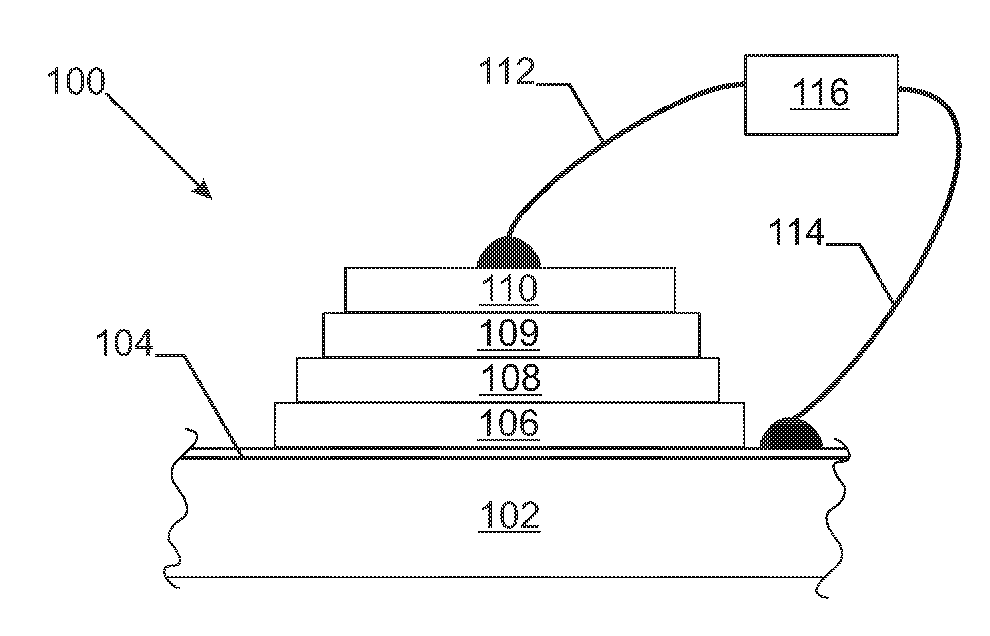
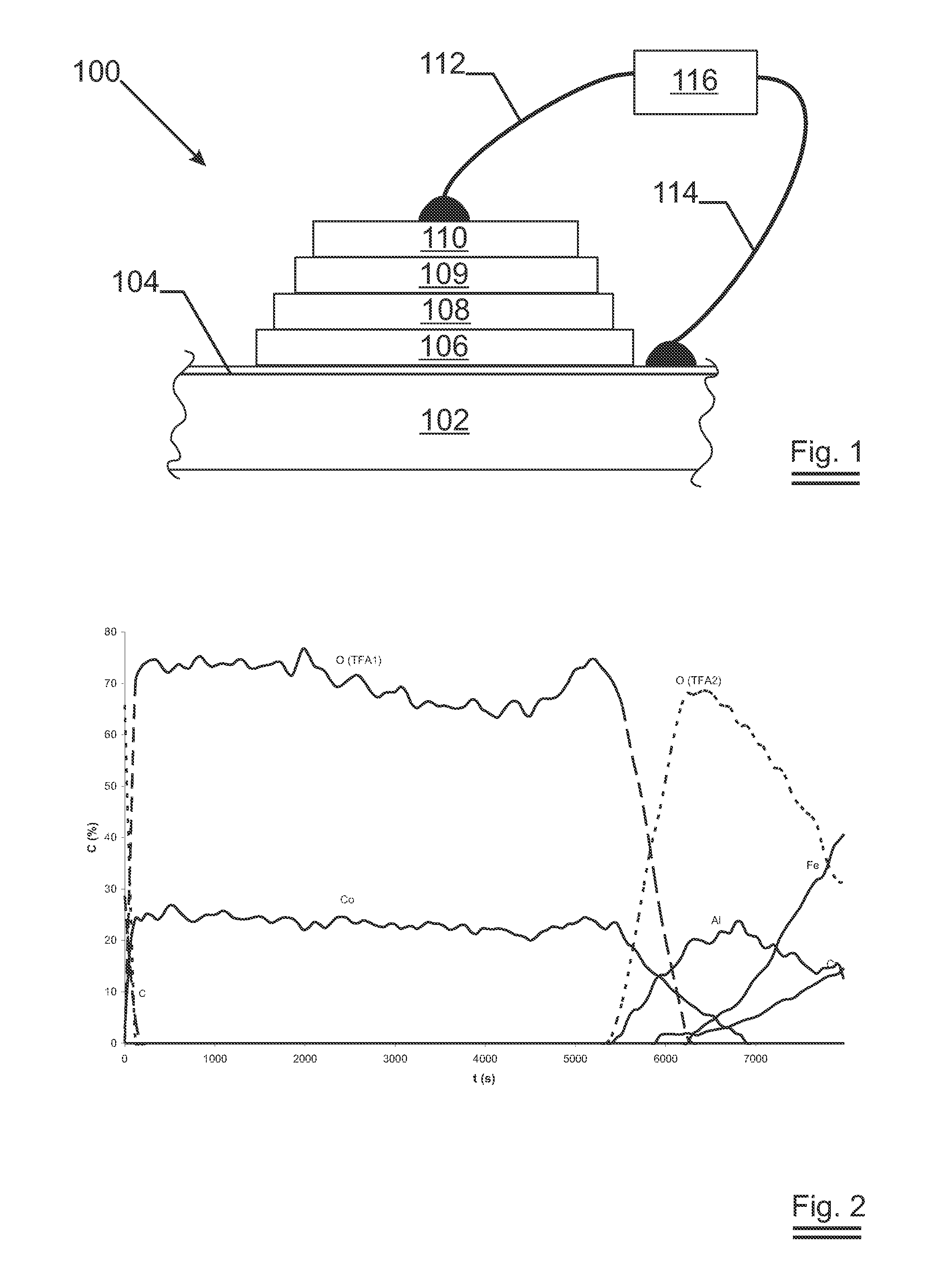
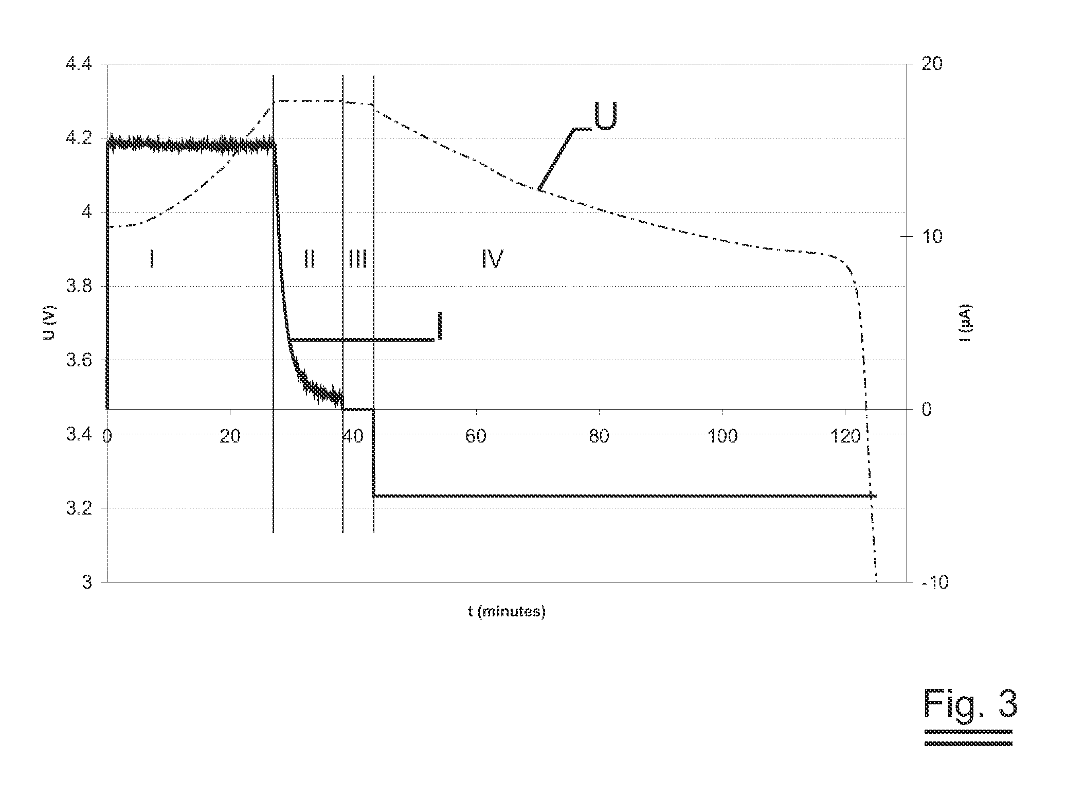

Image

  • Substrate for lithium thin film battery
  • Substrate for lithium thin film battery
  • Substrate for lithium thin film battery

Examples


Embodiment Construction

[0064]On a number of different metal alloy foils a first electrode material was deposited. The following compositions of alloys were selected (in % by weight of the total):

TABLE 1FoilMat. Nr.NiCrFeAlREPhADIN 1.47670.19*20.4*72.9*5.63*Y ≅ 0.06*FBDIN 1.476719-21Bal.5.5-6.0Zr > 0.03, Hf > 0.03, Y > 0.03FCDIN 1.476719-21Bal.5.0-6.00.15 > La > 0.01FDAISI 3016-9.5 16-19Bal.AEAISI 3017.5*16.5*Bal.AFAISI 3027.2*17.2*Bal.AGAISI 43016-18Bal.FHAISI 3048-10.518-20Bal.ADIN refers to the ‘Werkstoffnummer’,AISI refers to the ‘American Iron and Steel Institute’.RE are ‘reactive elements’.‘‘19-21’ means that the element concentration is between 19 and 21 percent by weight of the total,‘>0.10’ indicates the element is at least the percent in weight indicated.An asterisk ‘*’ indicates an actually measured value.‘Bal.’ indicates that - apart from the unintentional impurities - the remainder of the weight is made up by iron.The column ‘Ph.’ refers to the metallurgical phase the alloy is in: ‘F’ means ‘f...


PUM


Abstract

When attempting to make a lithium ion-switching device such as a high-efficiency, all-solid state, thin film battery the choice of carrier substrate is all important. As such a substrate must withstand a high temperature under an oxidising atmosphere to crystallise certain layers making up the device, the substrate should not oxidise thereby ruling out most metals. The invention now describes a class of ternary alloys of which the oxidation rate is limited and that are useable to produce thin film batteries on. At least one element with a high affinity to oxygen (Al, Mg, Zn or Si) is present in the alloy. The other two metallic elements reduce the growth of the oxide of this first element. In addition the thus formed oxide scale turns out to be an effective barrier to lithium. Surprisingly, the scale shows nanoscopic voids that allow for sufficient electrical contact with the device layers, thereby eliminating the need for a separate current collector. As the ternary alloy can be made in a flexible foil, it can advantageously be used in a roll-to-roll process.

Description

TECHNICAL FIELD[0001]The invention relates to the field of lithium ion-switching devices and more in particularly to secondary thin film batteries, having lithium as the mobile ion.BACKGROUND ART[0002]Rechargeable batteries—commonly called ‘secondary batteries’—are enjoying increased attention as the miniaturisation of electronic circuitry makes high tech appliances more mobile. As users, we expect those high-tech appliances and the battery that powers it:[0003]to be light in weight,[0004]to keep on operating for a long period of time without the need to recharge[0005]to recharge fast[0006]to be able to recharge many times without the operating period becoming shorter[0007]to be safe (non-explosive, non-flammable).Of course we don't want to pay too much for the whole system either i.e. the total device must be cost effectively designed and produced. As the rechargeable battery is one of the important costs of the whole, the battery should be likewise cheap.[0008]In the competition o...

Claims


Application Information

Patent Timeline
IPC IPC(8): H01M10/26H01M4/38H01M4/40H01M4/42H01M4/46H01M10/36
CPCH01M4/661H01M10/0585H01M10/0562H01M10/0525
Inventor LANGE, MARTINDEGRAER, CHRISTOPHE
Owner CYMBET CORP
Learn More