Ceramic honeycomb structure

a honeycomb and honeycomb technology, applied in the direction of physical/chemical process catalysts, separation processes, filtration separation, etc., can solve the problems of catalyst material corroding the honeycomb structure, easy eluted alkali elements of catalysts into water, performance degradation, etc., to reduce the temperature of burning soot and easy elute into water

Inactive Publication Date: 2010-04-29
DENSO CORP
View PDF18 Cites 1 Cited by
  • Summary
  • Abstract
  • Description
  • Claims
  • Application Information

AI Technical Summary

Benefits of technology

[0015]The catalyst described in the above-mentioned Patent Document 1 can decrease the temperature for burning soot as the concentration of alkali element becomes high. That is, the alkali-based catalyst material has positive and negative correlation between the concentration of alkali element and an activity temperature of the catalyst material. On the other hand, the catalyst material has a positive relationship between the alkali element concentration and an alkali element solubility of the catalyst material in water. That is, as the alkali element concentration of the catalyst becomes high, the alkali element of the catalyst is easily eluted into water.

Problems solved by technology

That is, as the alkali element concentration of the catalyst becomes high, the alkali element of the catalyst is easily eluted into water.
As a result, since the honeycomb catalyst is easily corroded by the alkali element, the alkali-based catalyst material may corrode the honeycomb structure.
Furthermore, after the alkali element is eluted, the catalyst has its performance degraded, so that the purification of the exhaust gas is not performed sufficiently.
The silver oxide described in the above-mentioned Non-Patent Document 1 releases oxygen owned by decomposition when burning soot once, and thus does not easily return to the original oxide.
Furthermore, the silver oxide tends to flocculate after being decomposed, resulting in a great reduction in activity.
When being used in an environment including sulfur, an exposed silver disadvantageously becomes silver sulfide and loses activity.

Method used


Image

  • Ceramic honeycomb structure
  • Ceramic honeycomb structure
  • Ceramic honeycomb structure

Examples


example 1

[0060]In the present example, a delafossite-type AgAlO2 is manufactured as the catalyst material and the catalyst characteristics thereof are evaluated. A manufacturing method of the catalyst material in the present example is the above-mentioned first hydrothermal synthesis method which involves base material synthesis, hydrothermal synthesis, water washing, ammonia washing, second water washing, and drying.

[0061]First, in the base material synthesis, a uniform mixture of an alkali salt (for example, sodium nitrate or the like) and an aluminum salt (for example, aluminum nitrate) are thermally decomposed at a temperature of 800 to 1000° C., thereby synthesizing sodium aluminate (NaAlO2) serving as the base material.

[0062]Then, the base material synthesized and silver oxide (Ag2O) are encapsulated into a pressure vessel and subjected to the hydrothermal treatment at a temperature of 150 to 180° C., thereby obtaining the delafossite-type AgAlO2 containing the Ag compound. The thus-ob...

example 2

[0080]In the present example, a ceramic honeycomb structure supporting the catalyst material (specimen A1) manufactured in Example 1 is manufactured.

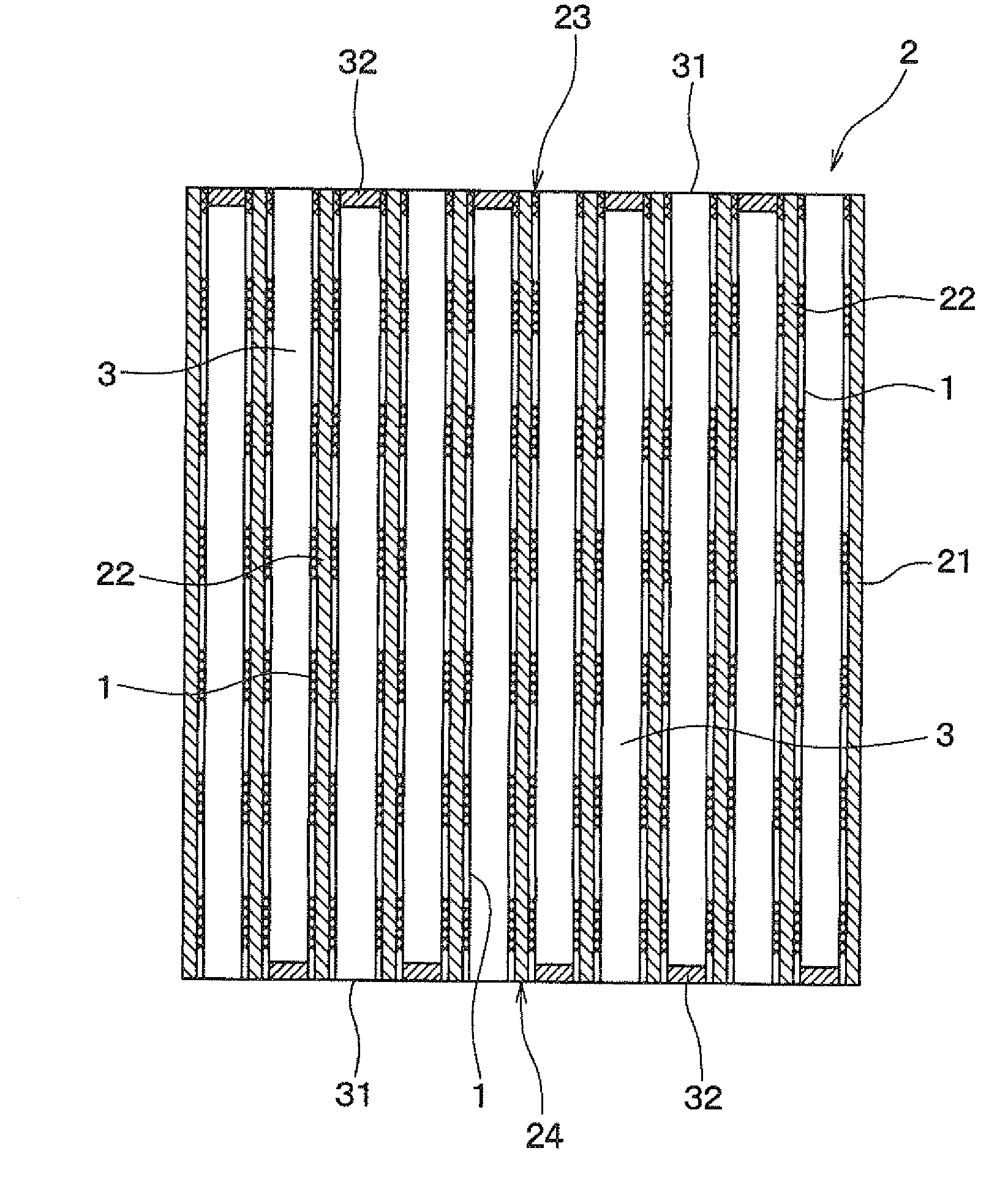
[0081]FIG. 3 is a perspective view of the ceramic honeycomb structure 2 of Example 2, FIG. 4 is a sectional view of the ceramic honeycomb structure 2 of Example 2 in the longitudinal direction, and FIG. 5 shows a state in which exhaust gas 10 passes through the ceramic honeycomb structure 2 of Example 2.

[0082]As shown in FIGS. 3 to 5, the ceramic honeycomb structure 2 of the present example includes an outer peripheral wall 21, partition walls 22 provided in the form of honeycomb inside the outer peripheral wall 21, and a plurality of cells 3 partitioned by the partition walls 22.

[0083]The cell 3 is partly opened at both ends 23 and 24 of the ceramic honeycomb structure 2. That is, parts of cells 3 are opened to both ends 23 and 24 of the honeycomb structure 2, and the remaining cells 3 are closed by stoppers 32 formed on the both ends ...

example 3

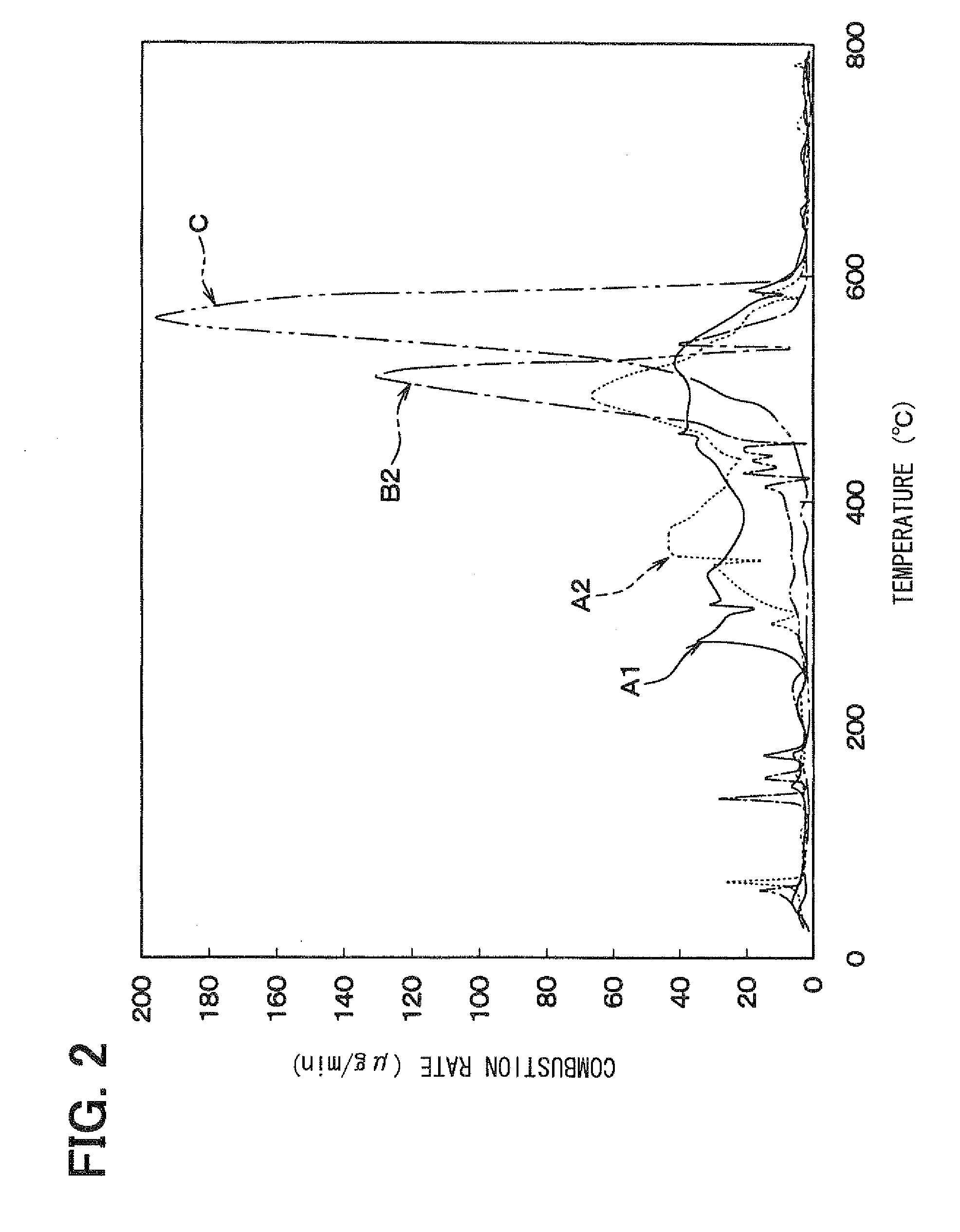
[0101]In Example 3, the combustion temperature of delafossite-type CuAlO2 was compared with that of the specimen A1 which was the delafossite-type AgAlO2 manufactured in Example 1. The comparison among both specimens was performed by measuring the heat balance and change in weight of carbon fines in heating each catalyst material together with the carbon fines by use of a differential thermogravimetric simultaneous measurement device in the same way as that shown in FIG. 2.

[0102]FIG. 12 is a diagram showing a relationship between the change in weight and heating temperature of the delafossite-type AgAlO2 (specimen A1) and the delaffosite type CuAlO2. The delaffosite type CuAlO2 was manufactured by burning a mixture of copper oxide and aluminum nitrate at a temperature of 1100° C. for four hours. As can be seen from FIG. 12, it is found that the delafossite-type CuAlO2 does not have low-temperature combustion characteristics over a wide range of low temperature, unlike Example 1.

[010...


PUM

PropertyMeasurementUnit
temperatureaaaaaaaaaa
thicknessaaaaaaaaaa
thicknessaaaaaaaaaa

Abstract

A ceramic honeycomb structure includes an outer peripheral wall, partition walls provided in the form of a honeycomb inside the outer peripheral wall, and a plurality of cells partitioned by the partition walls and at least partly penetrating both ends of the structure. In the ceramic honeycomb structure, a catalyst material used for burning carbon and containing silver dispersed into layered alumina is supported on an inner surface of the plurality of cells. Thus, the ceramic honeycomb structure can burn soot at low temperature using the supported catalyst material without corroding the honeycomb structure

Description

CROSS REFERENCE TO RELATED APPLICATION[0001]This application is based on Japanese Patent Applications No. 2007-72627 filed on Mar. 20, 2007, No. 2007-284949 filed on Nov. 1, 2007, No. 2008-38488 filed on Feb. 20, 2008, and No. 2008-65362 filed on Mar. 14, 2008, the contents of which are incorporated herein by reference in its entirety.TECHNICAL FIELD[0002]The present invention relates to a ceramic honeycomb structure made of ceramic and adapted to support a catalyst material to be used for burning carbon.BACKGROUND ART[0003]In recent years, soot discharged from engine, such as a diesel engine or the like, has become a problem. A purification device including a catalyst made of platinum alumina or the like generally intervenes in an exhaust pipe of the engine to remove soot from an exhaust gas. The purification device accommodates a ceramic honeycomb structure for supporting the catalyst material in a container. The exhaust gas containing soot is allowed to pass through the container...

Claims


Application Information

Patent Timeline
Patent Type & Authority Applications(United States)
IPC IPC(8): B01J23/50B01J21/14B01J27/224B01J21/02
CPCB01D46/0061F01N2250/02B01D53/944B01D2255/104B01D2255/20707B01D2255/2092B01D2255/92B01D2257/702B01D2279/30B01J23/50B01J35/002B01J35/04B01J37/0215B01J37/10F01N3/0222F01N3/035B01D46/2418B01D46/82B01D39/14B01D39/20B01D46/42B01D53/94
Inventor HAYASHI, YASUSHI
Owner DENSO CORP
Why Eureka
Try Eureka