
Capacitive coupling type touch panel

a capacitive coupling and touch panel technology, applied in the field of capacitive coupling type touch panel and display device, can solve the problems of inability to detect a position, inability to input with resin pen or the like, etc., and achieve the effect of reducing volume, difficult to maintain load deforming characteristics, and reducing load deforming characteristics

Inactive Publication Date: 2010-05-06
JAPAN DISPLAY INC +1
View PDF17 Cites 107 Cited by
  • Summary
  • Abstract
  • Description
  • Claims
  • Application Information

AI Technical Summary

Benefits of technology

[0025]Because the insulating film has refractive index characteristics of 1.30 or more and 1.52 or less, a capacitive coupling type touch panel that is excellent in display performance when combined with a display device can be realized.
[0026]Further, due to the presence of a protective layer protecting the floating electrode in an upper layer of the floating electrode, the floating electrode itself is protected from damages caused by the load from outside, and the performance as the capacitive coupling type touch panel can be held. Further, the protective layer may be formed of a transparent substrate, which can protect the floating electrode itself from damages caused by the load from outside.
[0028]The space layer has a space thickness of 10 μm or more and 120 μm or less, whereby the floating electrode is pressed due to a load occurring when touched with a pen, the space layer is compressed to be deformed in a thickness direction due to the load, and the floating electrode and the XY-position coordinate electrode approach each other. Thus, when capacitive coupling occurs between the floating electrode and the XY-position coordinate electrode, a large ratio between a signal and a noise (S / N ratio) of the capacitive coupling can be taken before the approach of the floating electrode and the XY-position coordinate electrode and after the approach of the floating electrode and the XY-position coordinate electrode, and, hence, a position signal can be detected satisfactorily.
[0031]The liquid layer has a thickness of 10 μm or more and 120 μm or less, whereby the floating electrode is pressed due to a load occurring when touched with a pen, the liquid layer is deformed in a thickness direction due to the load, and the floating electrode and the XY-position coordinate electrode approach each other. Thus, when capacitive coupling occurs between the floating electrode and the XY-position coordinate electrode, a large ratio between a signal and a noise of the capacitive coupling can be taken before the approach of the floating electrode and the XY-position coordinate electrode and after the approach of the floating electrode and the XY-position coordinate electrode, and hence, a position signal can be detected satisfactorily.
[0034]Because the liquid layer has refractive index characteristics of 1.30 or more and 1.52 or less, a capacitive coupling type touch panel excellent in display performance when combined with a display device can be realized.
[0044]An example of the material for a resin includes a silicone gel material. The silicone gel is an addition polymerization type silicone resin obtained by adding silicone oil to a monomer of silicone rubber due to the action of a platinum catalyst or the like, followed by curing at a cross-linking density of ⅕ to 1 / 10 of that of an ordinary silicone elastomer. The rubber material generally has a repulsion modulus of elasticity which varies remarkably depending upon a change in temperature due to the dependence of physical properties on the temperature, and becomes hard at a low temperature of about −10° C. and has load deforming characteristics decreased. Further, rubber has large permanent compression set (residual compression set). When the rubber is supplied with a load for a long period of time, the rubber is reduced in volume, which makes it difficult to maintain load deforming characteristics. In contrast, the gel material can obtain satisfactory load deforming characteristics with almost constant mechanical properties (Young's modulus, which can also be referred to as softness) even in an environment of about −50° C. to 200° C. Further, the gel material has a small residual compression set, and, hence, can maintain satisfactory load deforming characteristics for a long period of time. The silicone gel material has high light transmittance in a visible light region and can maintain light transmittance characteristics of 80% or more. Further, the silicone gel material, which has the refractive index characteristics of 1.30 or more and 1.52 or less, can realize a display device that is excellent in display performance.

Problems solved by technology

When a general capacitive coupling type touch panel is touched with a perfect insulator, static electricity on the surface is unlikely to change, which makes it impossible to detect a position.
Therefore, the input with a resin pen or the like cannot be performed, and a touch pen with conductivity is required.

Method used


Image

  • Capacitive coupling type touch panel
  • Capacitive coupling type touch panel
  • Capacitive coupling type touch panel

Examples


embodiment 1

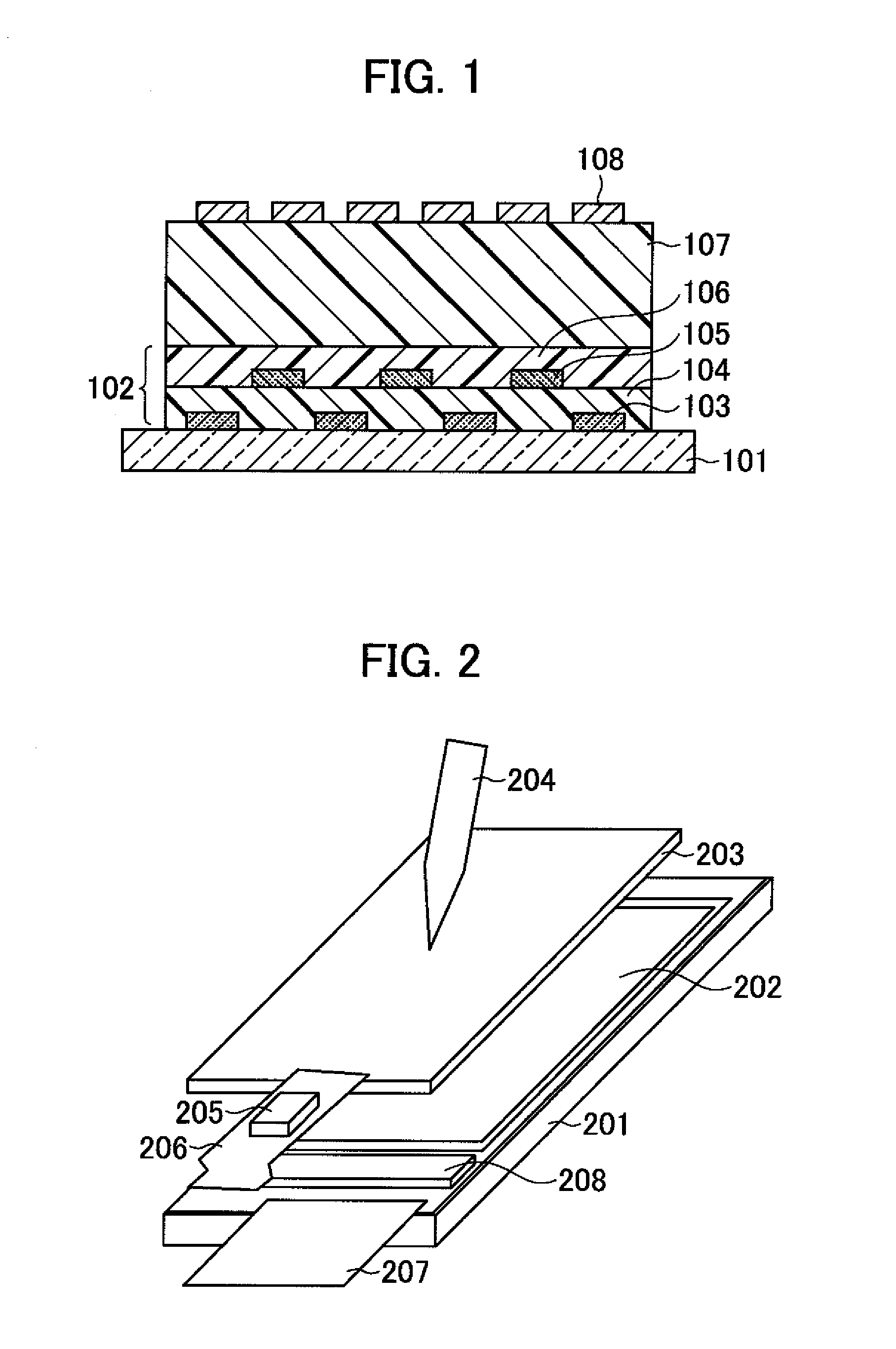
[0069]A touch panel device of Embodiment 1 illustrated in the cross-sectional view of FIG. 1 is produced under the following conditions.

[0070]In the touch panel device of this embodiment, a coordinate detection circuit layer 102 that detects a position coordinate is formed on one surface of a transparent substrate 101. In the circuit layer, transparent electrodes to be coordinate electrodes 103 and 105 are placed via insulating films 104 and 106.

[0071]As the transparent substrate 101, a glass substrate made of alkali glass such as soda glass or borosilicate glass, non-alkali glass, or chemically strengthened glass is suitable. In addition, polyester films having transparency such as polyethylene terephthalate and polyethylene naphthalate and polyimide films having high heat resistance and high transparency are also known, and such resin-based substrate having transparency may also be used. As the transparent electrodes to be the coordinate electrodes 103 and 105, oxide transparent e...

embodiment 2

[0097]A liquid crystal display device with a touch panel of Embodiment 2 illustrated in FIG. 2 is produced under the following conditions.

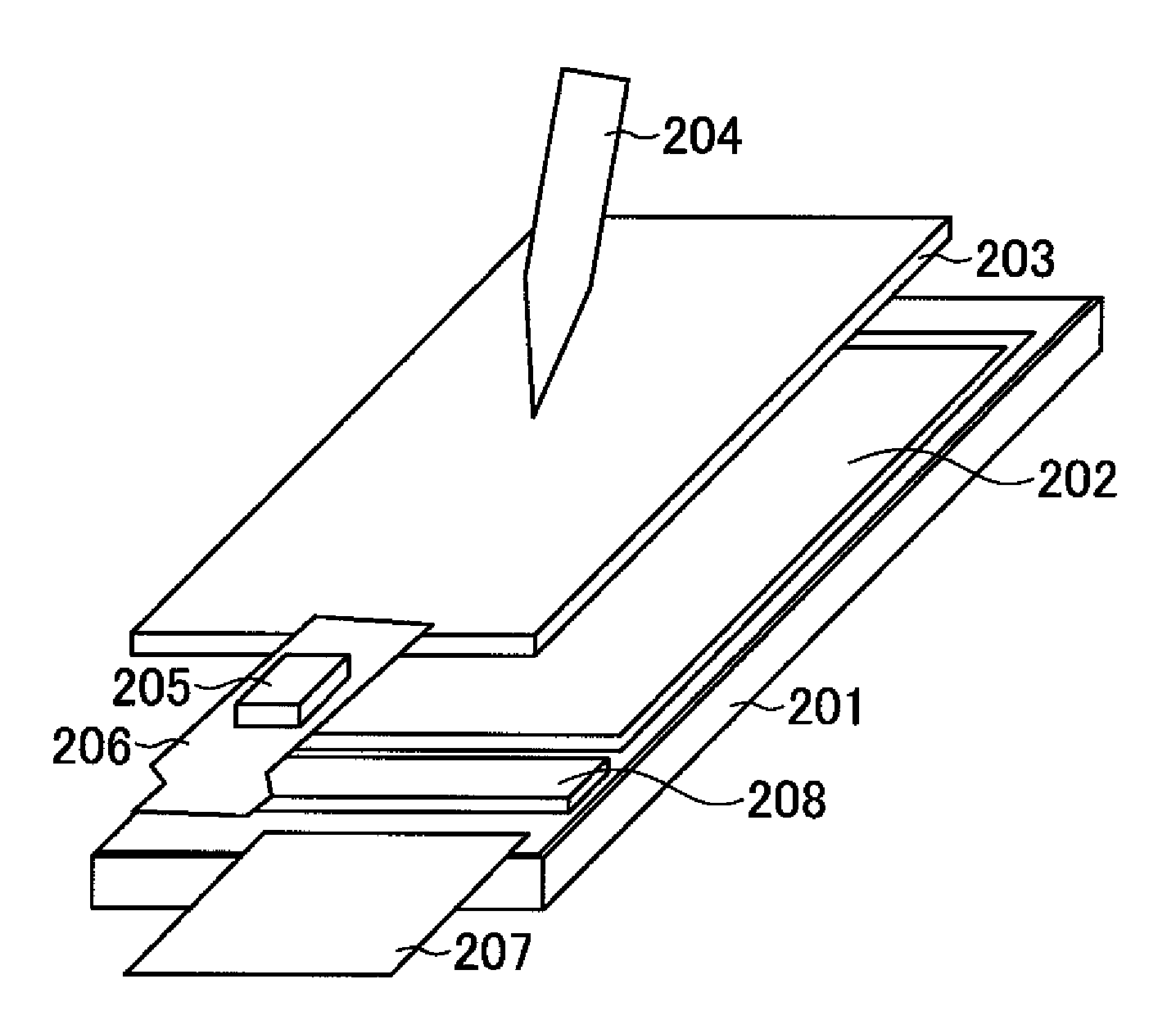
[0098]A touch panel 203 obtained in Embodiment I (FIG. 1) is laminated and fixed on a surface of a liquid crystal display device 201 opposed to a liquid crystal display region 202. The touch panel 203 is connected to a flexible printed wiring board 206 with a touch panel position detecting circuit control IC 205 mounted thereon. The flexible printed wiring board 206 connects the touch panel 203 to the liquid crystal display device 201 for the purpose of inputting a signal to the liquid crystal display device 201. A liquid crystal display control IC 208 is mounted on the liquid crystal display device 201, and a flexible printed wiring board 207 is connected thereto. The flexible printed wiring board 207 is connected to, for example, a signal circuit of a mobile phone, thereby sending a display image signal to the liquid crystal display device 201.

[...

embodiment 3

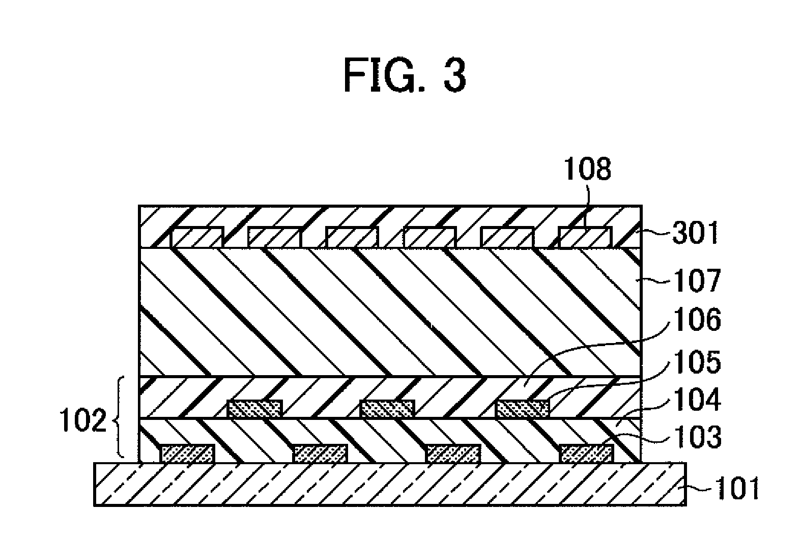
[0101]A touch panel device of Embodiment 3 illustrated in FIG. 3 is produced under the following conditions.

[0102]A surface protective layer 301 is formed on the outermost surface of the touch panel obtained in Embodiment 1 (FIG. 1).

[0103]As a material for the protective layer, an insulating film material with light transmittance that is used for the insulating films 104 and 106 in Embodiment 1 is suitable.

[0104]Further, in addition to the above-mentioned photosensitive material, a thermosetting material is also suitable in which only a thermosetting material is combined with a base polymer including an acrylic resin, an acrylic epoxy-based resin, or a siloxane-based resin.

[0105]Further, a glass substrate made of alkali glass such as soda glass or borosilicate glass, non-alkali glass, or chemically strengthened glass can be attached to be used as the surface protective layer 301. Further, a resin-based substrate having transparency, such as a polyester film made of polyethylene tere...


PUM


Abstract

A capacitive coupling type touch panel includes an XY-coordinate electrode configured to detect an XY-position coordinate. The XY-coordinate electrode is provided on a transparent substrate and detects a position inputted by capacitive coupling. The capacitive coupling type touch panel also includes an electrode provided at a position so as to be isolated from and opposed to the XY-coordinate electrode.

Description

CROSS-REFERENCE TO RELATED APPLICATIONS[0001]The present application claims priority from Japanese Applications JP2008-285548 filed Nov. 6, 2008 and JP2009-053043 filed Mar. 6, 2009, the contents to which are hereby incorporated by reference into this application.BACKGROUND OF THE INVENTION[0002]1. Field of the Invention[0003]The present invention relates to a capacitive coupling type touch panel and a display device on which the touch panel is mounted. In particular, the present invention relates to a capacitive coupling type touch panel adapted for a resin pen input.[0004]2. Description of the Related Art[0005]A touch panel is an appliance that has, when combined with a display device, a function of detecting a position when a touch panel screen corresponding to a display area of the display device is touched (pressed) with a finger or a pen and inputting a position coordinate and the like to the display device.[0006]Due to the operation principle, various types are available for ...

Claims


Application Information

Patent Timeline
IPC IPC(8): G06F3/044G06F3/045
CPCG06F3/044G06F3/0447G06F3/0445G06F3/0412G06F2203/04111G06F3/0448G06F3/04166H10K59/40
Inventor TANAKA, JUNSEKIGUCHI, SHINJIMAMBA, NORIOHAMAMOTO, TATSUO
Owner JAPAN DISPLAY INC
Learn More