Metal polishing slurry and polishing method
a metal polishing slurry and polishing technology, applied in lapping machines, manufacturing tools, other chemical processes, etc., can solve the problems of unfavorable dissolution of the concave regions of the metallic film, damage to the planarizing effect, and inability to easily subject copper or copper alloys to fine processing based on dry etching, etc., to achieve no scratches, large polishing, and high polishing
- Summary
- Abstract
- Description
- Claims
- Application Information
AI Technical Summary
Benefits of technology
Problems solved by technology
Method used
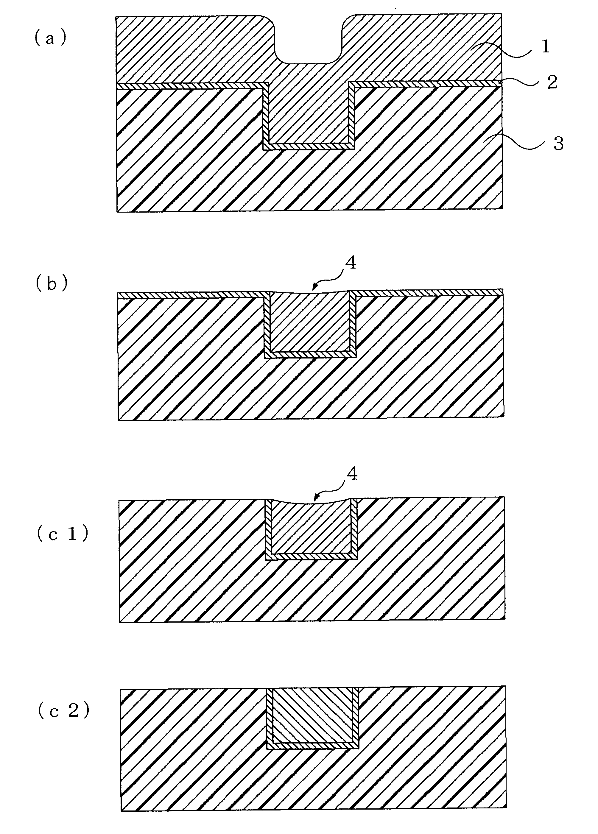
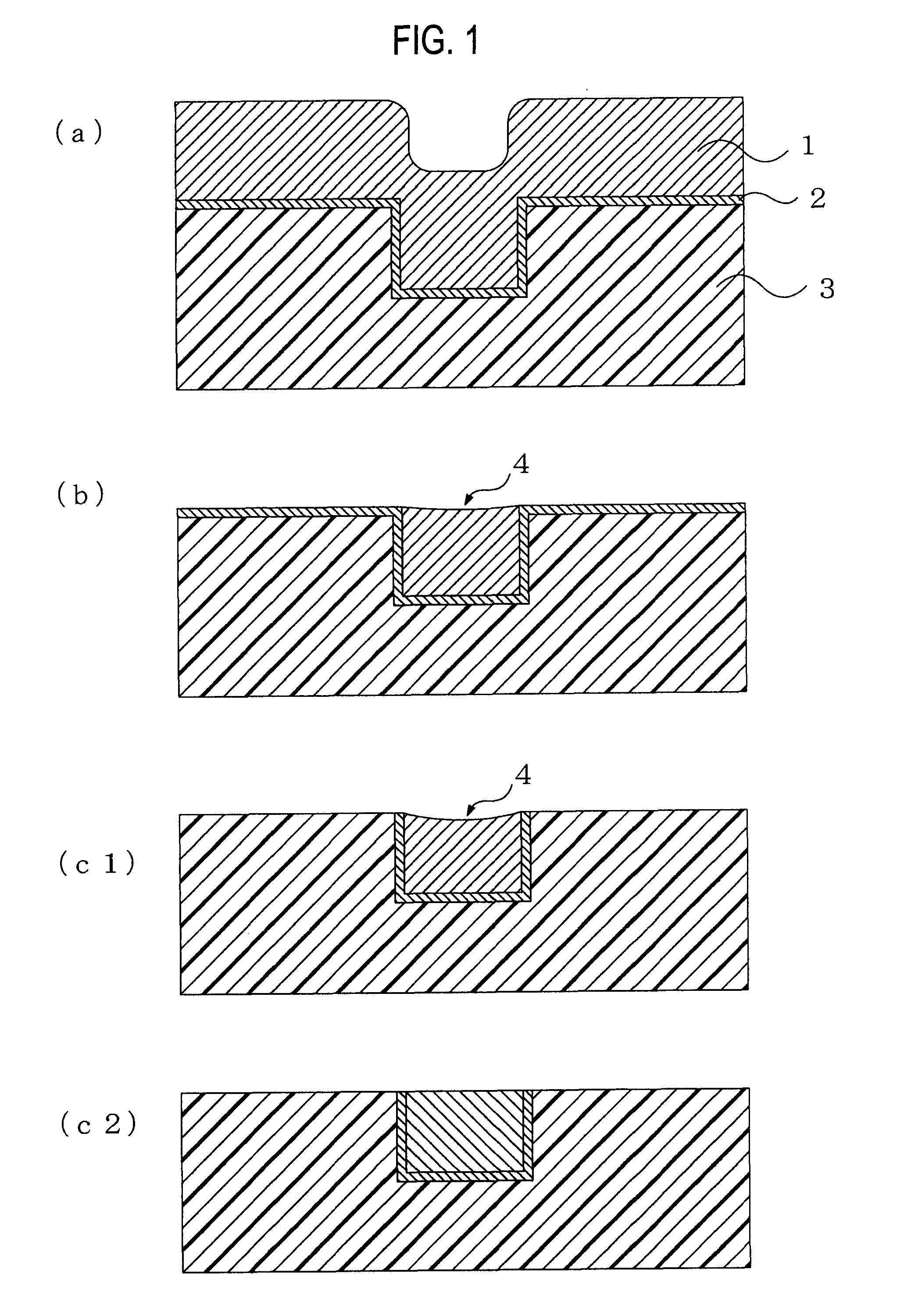
Image

Examples
examples
[0088]The invention will be described by way of examples hereinafter. However, the invention is not limited by these examples.
examples 1 to 8
, and Comparative Examples 1 to 2
(Polishing Slurry Producing Method)
[0089]Some materials shown in Table 1 were mixed with each other in individual amounts (parts by mass) to prepare each of metal polishing slurries used in Examples 1 to 8 and Comparative Examples 1 to 2. The metal polishing slurry was used to polish each of substrates yielded described below under polishing conditions described below.
(Method for Measuring the Average Secondary Particle Diameter)
[0090]The average secondary particle diameter of abrasive grains was measured with a submicro particle analyzer (machine name: N5 Submicron Particle Size Analyzer, manufactured by Beckman Coulter, Inc.) based on the dynamic scattering method.
(Method for Measuring Average Primary Particle Diameter)
[0091]About the average primary particle diameter of abrasive grains, an ultra high resolving-power electron microscope (SEM) (machine name: Hitachi S-4800, manufactured by Hitachi Kyowa Engineering Co., Ltd.) was used to take a phot...
PUM
| Property | Measurement | Unit |
|---|---|---|
| Percent by mass | aaaaa | aaaaa |
| Percent by mass | aaaaa | aaaaa |
| Particle diameter | aaaaa | aaaaa |
Abstract
Description
Claims
Application Information
 - R&D
- Intellectual Property
- Life Sciences
- Materials
- Tech Scout
- Unparalleled Data Quality
- Higher Quality Content
- 60% Fewer Hallucinations
Browse by: Latest US Patents, China's latest patents, Technical Efficacy Thesaurus, Application Domain, Technology Topic, Popular Technical Reports.
© 2025 PatSnap. All rights reserved.Legal|Privacy policy|Modern Slavery Act Transparency Statement|Sitemap|About US| Contact US: help@patsnap.com