Distributed coexistence system for interference mitigation in a single chip radio or multi-radio communication device

a coexistence system and radio technology, applied in the field of data communication, can solve the problems of affecting the operation of the radio itself, the complexity of the implementation of the traditional rf circuit, and the inability to manufacture the mask adder of the rf/analog circuit,

Active Publication Date: 2010-06-03
TEXAS INSTR INC
View PDF13 Cites 161 Cited by
  • Summary
  • Abstract
  • Description
  • Claims
  • Application Information

AI Technical Summary

Benefits of technology

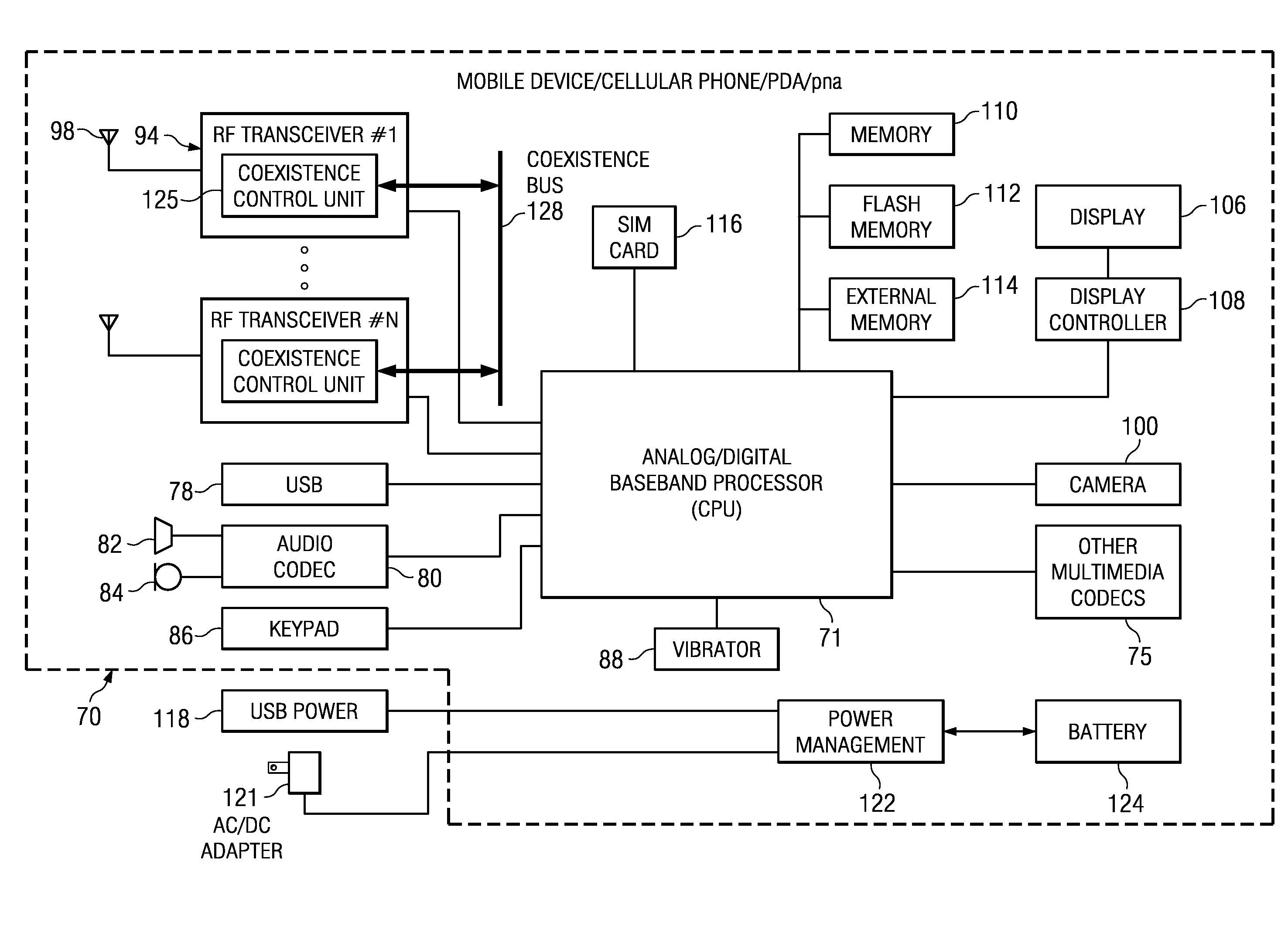
[0022]The present invention is a novel and useful apparatus for and method of distributed coexistence for mitigating interference in a single chip radio and / or a multi-radio (i.e. multi-transceiver) communications device. The coexistence mechanism of the present invention enables coexistence ‘friendly’ radio IPs that are capable of shifting their clock frequencies thereby avoiding frequency bands of potential victim radios. A coexistence mechanism attempts to solve the coexistence problem through frequency agility on the aggressor radio side (rather than by mitigating the effect of interference on the victim radio side) in order to avoid any harmonics from the aggressor's clock scheme falling in the operating frequency band of the victim radio, and in turn causing degradation to its performance.
[0023]In particular, the coexistence mechanism provides significant de-sense relaxation through interference avoidance without any extra requirements on the analog side (e.g., decoupling capacitors, isolation circuitry, etc.).
[0024]Depending on the specific implementation, the coexistence mechanism can operate with existing radios without requiring any significant changes to the existing radio. In one embodiment, the coexistence mechanism requires the addition of a clock generation circuit PLL and gating circuitry to the existing radio (i.e. IP).
[0029]Several advantages of the coexistence mechanism of the present invention include (1) the enablement of coexistence ‘friendly’ radios that are capable of shifting their own clocks so as to avoid interference with potential victim radio frequency bands; (2) the mechanism does not require extra analog components or other requirements; (3) the mechanism can be implemented entirely digitally (i.e. no analog constraints), and its performance is entirely predictable and can be simulated; and (4) depending on the particular implementation, the mechanism minimizes the additional required chip area and exhibits relatively low power consumption.
[0031]There is thus provided in accordance with the invention, a method of distributed coexistence between a plurality of aggressor and victim radios, the method comprising the steps of each victim radio communicating receiver (RX) information to all other radios and each aggressor radio configuring its root clock frequency based on received RX information so as to avoid interfering with the victim radios.

Problems solved by technology

This is an important issue in the design of multi-radio systems that is only gaining in criticality of operation as the number, complexity and frequency band use of radios increases with time.
The use of low-voltage deep submicron CMOS processes allows for an unprecedented degree of scaling and integration in digital circuitry, but complicates implementation of traditional RF circuits.
Furthermore, any mask adders for RF / analog circuits are not acceptable from a fabrication cost standpoint.
The clocks from one radio can interfere not only with the operation of other radios but with the operation of that radio itself.
In particular, in single chip wireless systems (i.e. systems with RF transceivers and digital logic), digital clocks can potentially leak into the RF antenna port or other parts of the system and desensitize the receivers.
Due to the very low input power required for good packet (or signal) reception and the relatively high currents drawn by the digital portions of the system, it is usually impossible to provide sufficient on-chip isolation between the digital circuitry and the RF circuit portion.
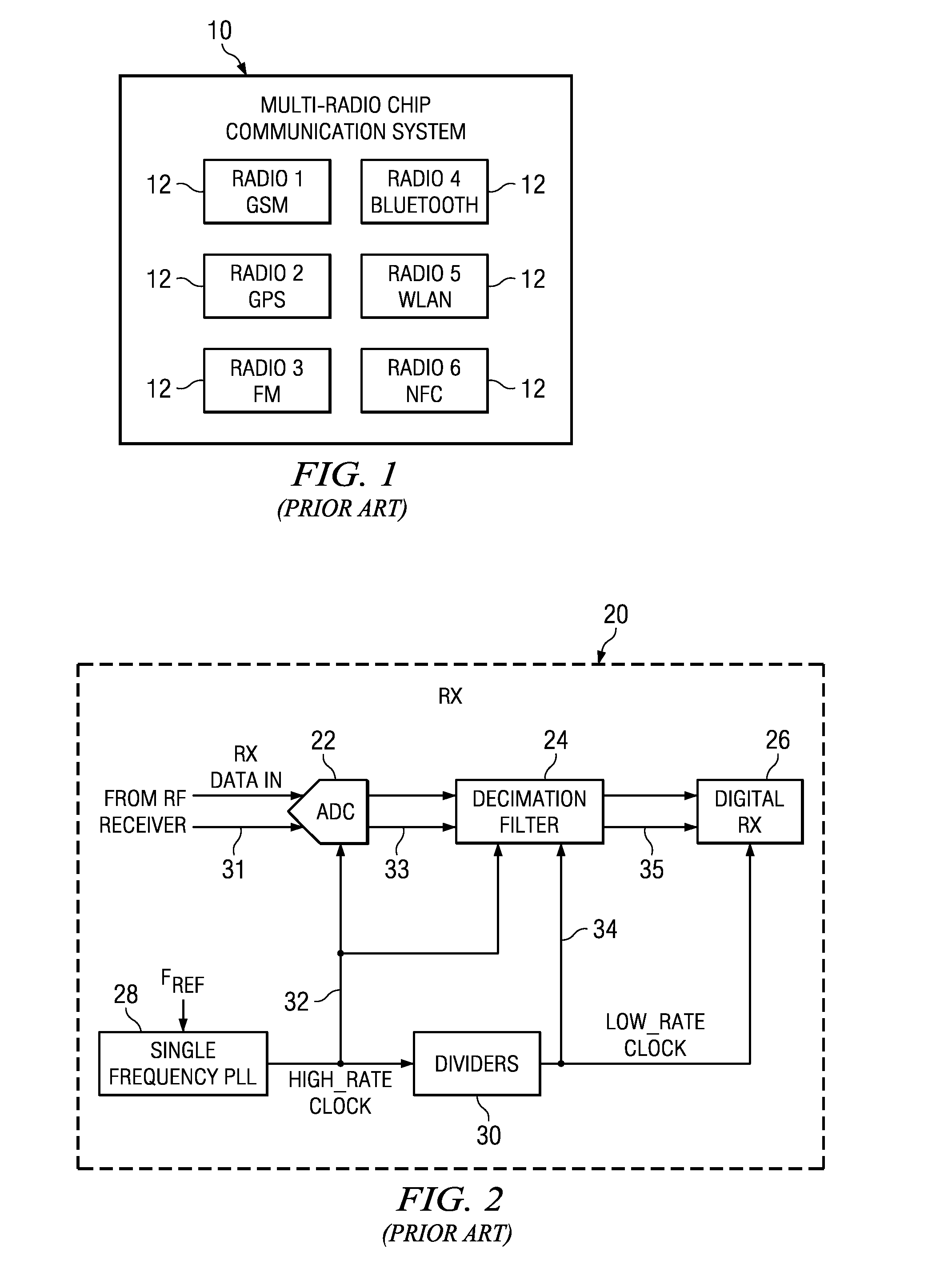
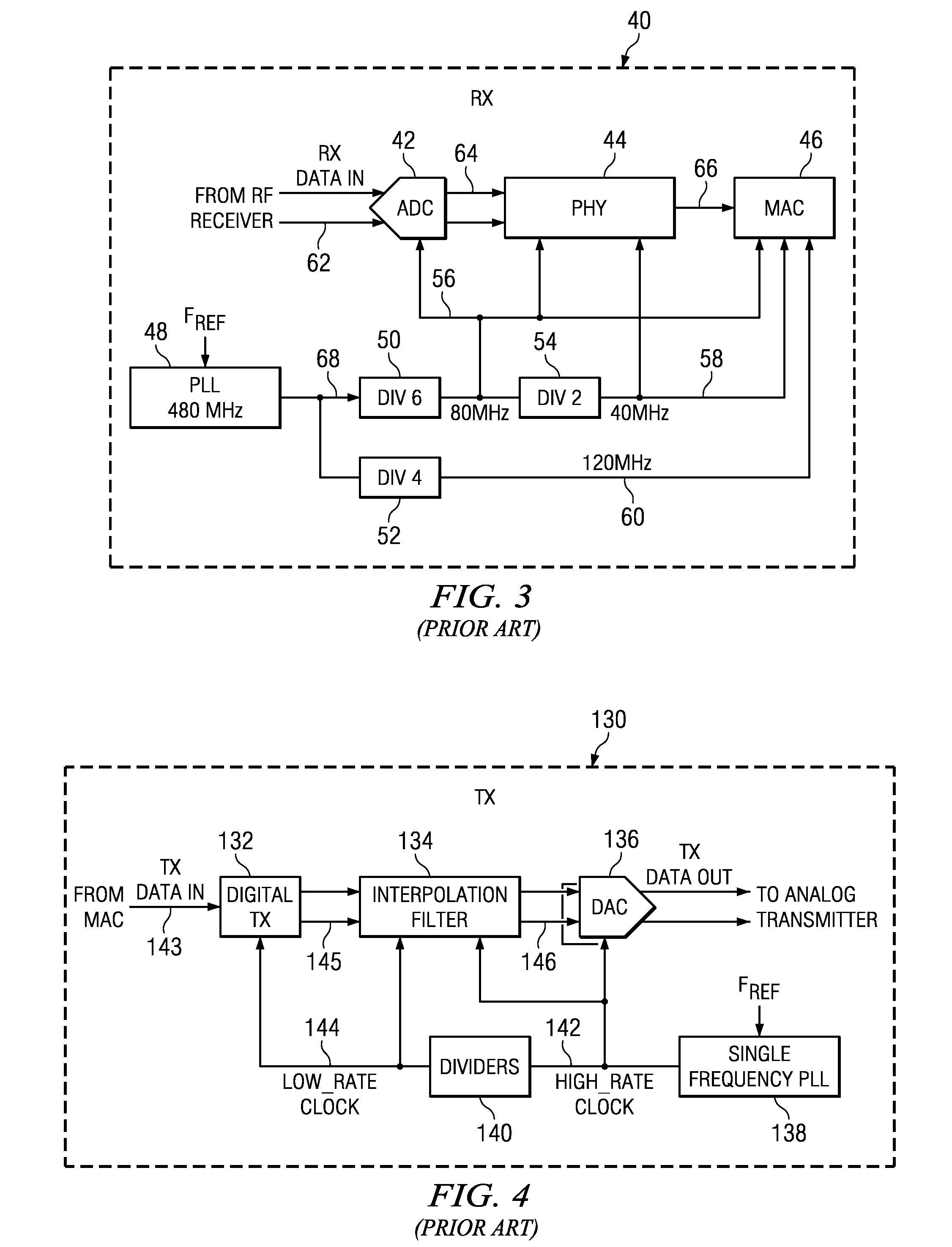
A major problem, however, associated with prior art clock generation schemes such as that of FIGS. 2, 3 and 4 is their inflexibility regarding their clock generation circuits.
The problems and issues raised related to implementing coexistence among the radios eventually affects system functionality by degrading it.
In particular digital clocks, their divisions or harmonics, driving large digital circuits, within one receiver or transmitter can interfere with other receivers.
The amount of isolation required in order to prevent de-sensitization in such a case can be impractical.
In addition, designing a system with such isolation between two points is a daunting task but many coupling paths between the aggressor and victim can exist making the task almost impossible.
A major disadvantage of this approach is that it typically only attenuates the spur and does not remove it completely.
In addition, such techniques require additional development time that increases system cost, require significant chip area also increasing cost and result in additional power consumption.
It is noted, however, that this technique is not always feasible as it requires a very careful physical layout, has a chip area penalty associated with it and any beneficial results can only be known after silicon is available.

Method used


Image

  • Distributed coexistence system for interference mitigation in a single chip radio or multi-radio communication device
  • Distributed coexistence system for interference mitigation in a single chip radio or multi-radio communication device
  • Distributed coexistence system for interference mitigation in a single chip radio or multi-radio communication device

Examples


Embodiment Construction

Notation Used Throughout

[0063]The following notation is used throughout this document.

TERM DEFINITION

[0064]AC Alternating Current[0065]ADC Analog to Digital Converter[0066]ASIC Application Specific Integrated Circuit[0067]AVI Audio Video Interface[0068]BMP Windows Bitmap[0069]BW Bandwidth[0070]CMOS Complementary Metal Oxide Semiconductor[0071]CPU Central Processing Unit[0072]DAC Digital to Analog Converter[0073]dB Decibel[0074]DC Direct Current[0075]DCXO Digitally Controlled Crystal Oscillator[0076]DRP Digital RF Processor or Digital Radio Processor[0077]DSL Digital Subscriber Line[0078]DSP Digital Signal Processor[0079]EDGE Enhanced Data Rates for GSM Evolution[0080]EEPROM Electrically Erasable Programmable Read Only Memory[0081]EM Electromagnetic[0082]EPROM Erasable Programmable Read Only Memory[0083]FCC Federal Communications Commission[0084]FCW Frequency Command Word[0085]FEM Front End Module[0086]FIFO First in First Out[0087]FM Frequency Modulation[0088]FPGA Field Programmable ...


PUM


Abstract

A novel and useful apparatus for and method of distributed coexistence for mitigating interference in a single chip radio and / or a multi-radio (i.e. multi-transceiver) communications device. The invention enables coexistence ‘friendly’ radio IPs having frequency agility in that they are capable of shifting their clock frequencies thereby avoiding frequency bands of potential victim radios. Frequency agility on the aggressor radio side (rather than by mitigating the effect of interference on the victim radio side) prevents harmonics from the aggressor's clock scheme from falling in the operating frequency band of the victim radio, and in turn causing degradation to its performance. Each aggressor radio, based on information received from other radios, configures the root clock frequency of its RX and / or TX chain clock generation circuits.

Description

FIELD OF THE INVENTION[0001]The present invention relates to the field of data communications and more particularly relates to coexistence for interference mitigation in a single chip radio and / or a multi-radio (i.e. multi-transceiver) communications device.BACKGROUND OF THE INVENTION[0002]Currently, many communication devices manufacturers are incorporating multiple radios into their products. As this trend continues, more and more radios will be integrated into the same communications device and / or onto the same integrated chip or system on a chip (SoC). In order for radios to be integrated onto the same chip, SoC or into the same device, it is critical that they coexist with each other. This is an important issue in the design of multi-radio systems that is only gaining in criticality of operation as the number, complexity and frequency band use of radios increases with time.[0003]As an example, consider the block diagram illustrating an example prior art multi-radio communicatio...

Claims


Application Information

Patent Timeline
Patent Type & Authority Applications(United States)
IPC IPC(8): H04M1/00H04B1/38
CPCH04B15/02H04B2215/064H04L12/413H04B3/32H04B2215/065
Inventor TAL, NIRTZOREFF, YANIVAMIDAN, MORANLERNER, GREGORYISAAC, RONENFAUST, ROI
Owner TEXAS INSTR INC
Why Eureka
Try Eureka