Power control unit for high-frequency dielectric heating and control method thereof

a technology of power control unit and high-frequency dielectric heating, which is applied in the direction of electric/magnetic/electromagnetic heating, climate sustainability, sustainable buildings, etc., can solve the problems of increasing the value of harmonic components, increasing the difficulty of suppressing the power supply harmonic current, and reducing the demand for miniaturization and weight reduction of power supplies. , to achieve the effect of reducing instantaneous fluctuation, simple configuration and stable output of magnetrons

Inactive Publication Date: 2010-06-24
PANASONIC CORP
View PDF8 Cites 14 Cited by
  • Summary
  • Abstract
  • Description
  • Claims
  • Application Information

AI Technical Summary

Benefits of technology

[0070]According to the invention, the input current waveform information of the inverter for rectifying the AC power supply voltage into an alternating current of a predetermined frequency is converted into a drive signal of the semiconductor switching element of the inverter so as to suppress instantaneous fluctuation. For example, the input current waveform information is converted into the on and off drive signals of the semiconductor switching element of the inverter according to the frequency modulation system for use. Therefore, the control loop for correcting the input current by raising the switching frequency in the portion where the input current is large and lowering the switching frequency in the portion where the input current is small is formed. Therefore, if variations in the magnetron type or characteristic, ebm (anode-to-cathode voltage) fluctuation according to the magnetron anode temperature or a load in a microwave oven, or power supply voltage fluctuation exists, input current waveform shaping not affected by the variations or the fluctuation can be carried out according to the simple configuration and stable output of the magnetron can be accomplished according to the simple configuration.
[0071]Since the input voltage waveform information is also input to the correction loop, the start time of the magnetron is shortened and the power factor at the low input current time is improved.

Problems solved by technology

Hitherto, a power supply installed in a high-frequency heating apparatus has been heavy and large and therefore there has been a demand for miniaturization and weight reduction of the power supply.
The switching mentioned above still involves a problem such that the current waveform of a commercial power supply supplied to the magnetron driving power supply becomes a waveform much containing a harmonic component combined with the fact that the magnetron is a nonlinear load indicated by the VAK (anode cathode voltage)-lb characteristic in FIG. 63.
On the other hand, the absolute value of the harmonic component becomes higher with an increase in power consumption of the magnetron driving power supply to satisfy the requirement for shortening the cooking time of a microwave oven and it is made more difficult to suppress the power supply harmonic current.
However, the nonlinear characteristic of the magnetron varies from one magnetron type to another and also fluctuates due to the magnetron temperature and a heated substance (load) in a microwave oven.
The apparatus in the prior art cannot deal with the problems.
Then, producing a high-frequency dielectric heating circuit not affected by the magnetron type is a problem.
Since the nonlinear characteristic of the magnetron also thus varies largely depending on whether the impedance matching is good or poor, producing a high-frequency dielectric heating circuit not affected by the magnetron type is a problem.
Therefore, if the magnetron temperature is matched with a low temperature, when the magnetron temperature becomes high, the input current waveform is distorted.
Since the nonlinear characteristic of the magnetron also thus varies largely due to the magnetron temperature difference, producing a high-frequency dielectric heating circuit not affected by the magnetron type is a problem.

Method used


Image

  • Power control unit for high-frequency dielectric heating and control method thereof
  • Power control unit for high-frequency dielectric heating and control method thereof
  • Power control unit for high-frequency dielectric heating and control method thereof

Examples


embodiment 1

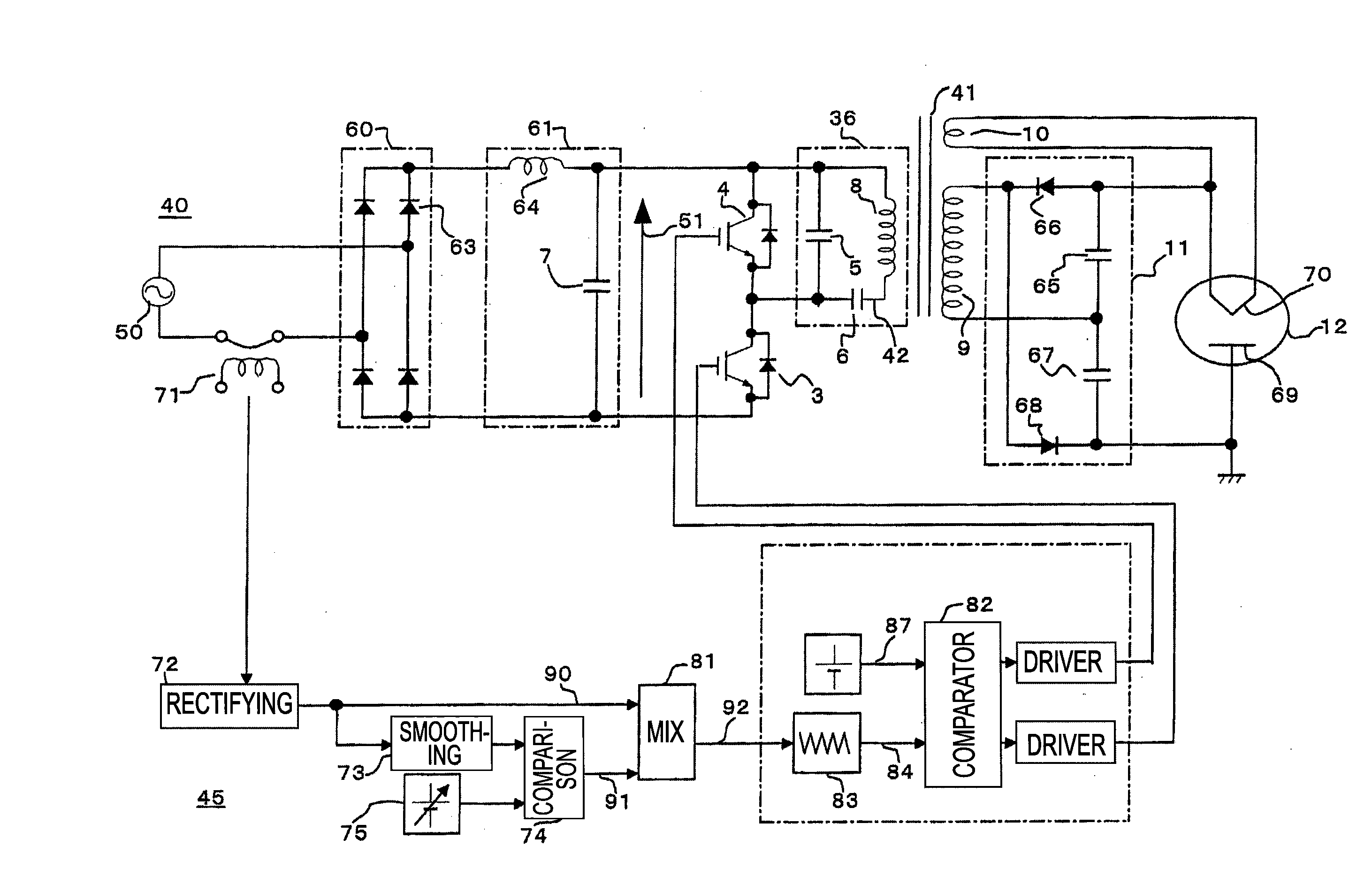
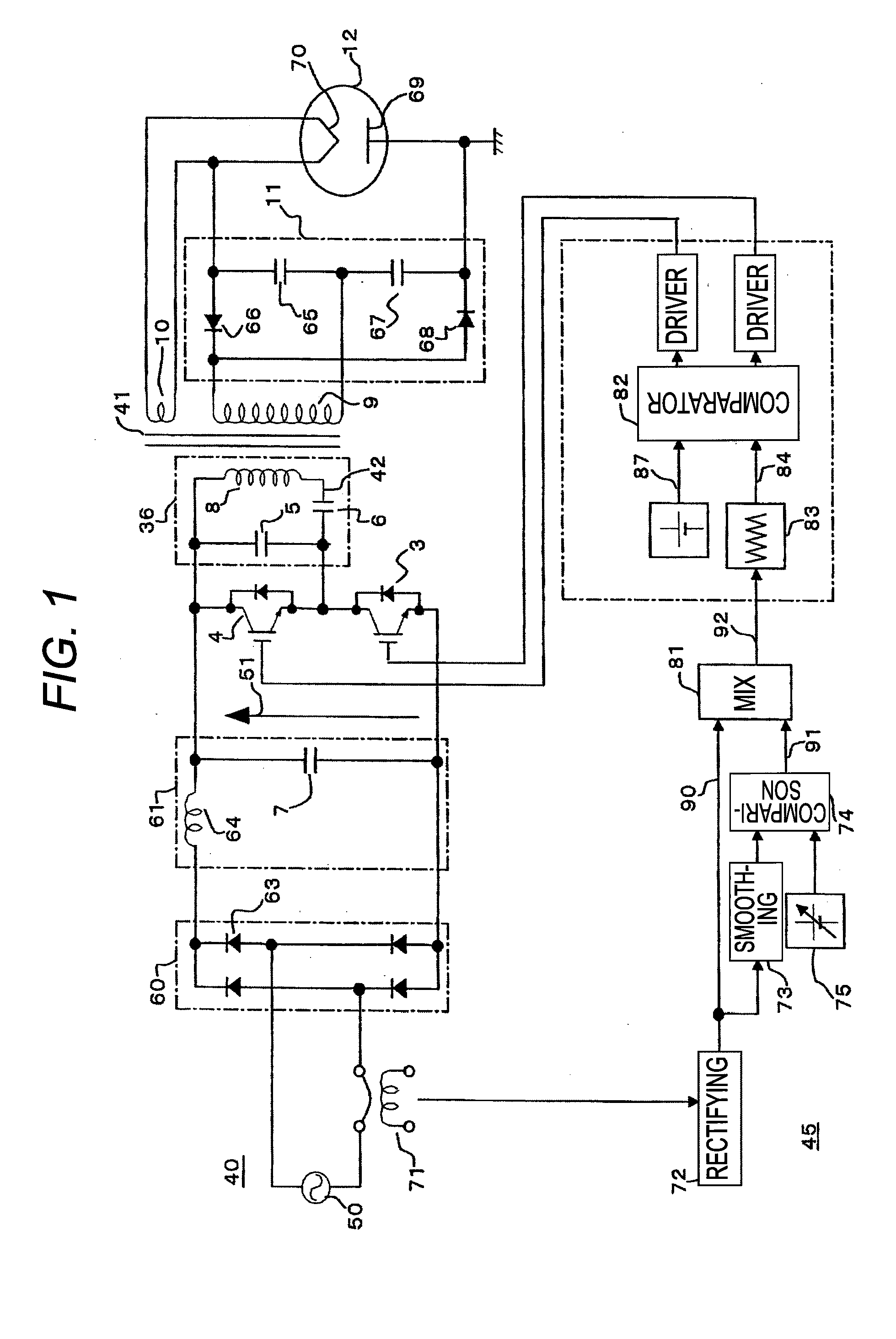
[0196]FIG. 1 is a block diagram to describe a high-frequency heating apparatus according to embodiment 1 of the invention. In FIG. 1, the high-frequency heating apparatus is made up of an inverter 40, a controller 45 for controlling first and second semiconductor switching elements 3 and 4 of the inverter, and a magnetron 12. The inverter 40 contains an AC power supply 50, a diode bridge type rectifier 60, a smoothing circuit 61, a resonance circuit 36, the first and second semiconductor switching elements 3 and 4, and a voltage-doubling rectifier 11.

[0197]An AC voltage of the AC power supply 50 is rectified in the diode bridge type rectifier 60 made up of four diodes 63 and is converted into a DC power supply 51 through the smoothing circuit 61 made up of an inductor 64 and a third capacitor 7. Then, it is converted into a high-frequency AC by the resonance circuit 36 made up of a first capacitor 5, a second capacitor 6, and a primary winding 8 of a transformer 41 and the first and...

embodiment 2

[0231]Next, embodiment 2 of the invention will be discussed. Embodiment 2 of the invention relates to the configuration of a controller and has the configuration wherein in FIG. 1, the input current waveform information 90 and the power control information 91 from the comparator 74 are mixed and filtered and converted into on and off drive signals of the semiconductor switching element 3, 4 of the inverter for use. Accordingly, it is not necessary to process commercial power supply voltage waveform information conforming to the nonlinear load characteristic of a magnetron, a frequency modulation signal generator is simplified, and the commercial power supply voltage waveform information also becomes unnecessary as compared with the prior art example in FIG. 64, so that practical miniaturization of the machine configuration is facilitated, the control procedure is simplified, and the processing time can be shortened and thus the reliability of the machine can also be improved.

[0232]T...

embodiment 3

[0233]Embodiment 3 of the invention relates to an input current detection section. In FIG. 1, the input current detection section detects the input current of the inverter with the CT 71, etc., and performs rectification output from the rectifier 72. According to the configuration, the input current is detected using the CT, etc., and thus a large signal can be taken out while insulating property is maintained, so that the effect of input current waveform shaping is large and the quality of the input current is improved.

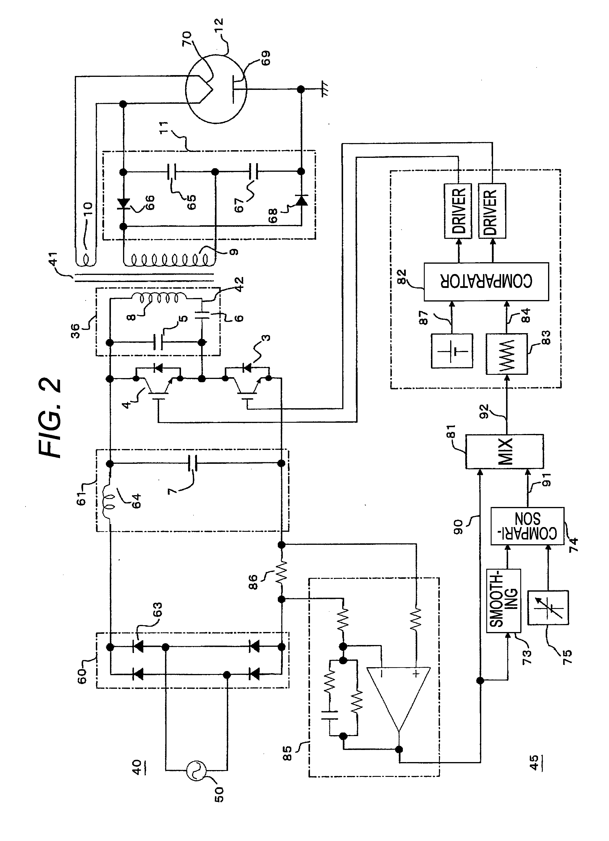
[0234]In the example shown in FIG. 2, the input current detection section detects the unidirectional current after rectified in the rectifier 61 of the inverter through the shunt resistor 86 placed between the rectifier 60 and the smoothing circuit 61, amplifies the voltage occurring across the shunt resistor 86 by the amplifier (amplifier) 85, and outputs the voltage. The configuration has the advantage that the input current detection section can be configured at a...


PUM


Abstract

A power control unit for a high-frequency dielectric heating not affected by variations in the magnetron type or characteristic, and power supply voltage fluctuation, etc., is provided. The power control unit for a high-frequency dielectric heating has an input current detection section 71, 72 for detecting input current of an inverter 10 for rectifying 31 an AC power supply voltage 20, performing high-frequency switching of the voltage, and converting the voltage to high-frequency power. The power control unit for a high-frequency dielectric heating converts a switching frequency control signal 92 provided by mixing input current waveform information 90 and power control information 91 into a drive signal of a semiconductor switching element 3, 4 of the inverter.

Description

[0001]This application is a division of U.S. patent application Ser. No. 12 / 303,035 filed Dec. 1, 2008, which is incorporated herein by reference in its entirety.TECHNICAL FIELD[0002]This invention relates to high-frequency dielectric heating power control using a magnetron and in particular to high-frequency dielectric heating not affected by characteristic variations in magnetrons, the magnetron type, or the difference of the anode temperature, etc., of a magnetron.BACKGROUND ART[0003]Hitherto, a power supply installed in a high-frequency heating apparatus has been heavy and large and therefore there has been a demand for miniaturization and weight reduction of the power supply. Thus, miniaturization, weight reduction, and cost reduction by switching the power supply have been advanced aggressively in current various fields. In a high-frequency heating apparatus for cooking food by a microwave generated in a magnetron, miniaturization and weight reduction of the power supply for d...

Claims


Application Information

Patent Timeline
Patent Type & Authority Applications(United States)
IPC IPC(8): H05B6/68
CPCY02B40/143H05B6/685Y02B40/00
Inventor SUENAGA, HARUOYASUI, KENJISAKAI, SHINICHISHIROKAWA, NOBUOMORIYA, HIDEAKIKINOSHITA, MANABU
Owner PANASONIC CORP
Why Eureka
Try Eureka