Receiver with tuner front end using tracking filters and calibration

a technology of tracking filter and receiver, applied in the field of communication systems, can solve the problems of limited tuning range, increased cost and space usage, and inability to optimize the design of the receiver for cost and/or performance, and achieves the effect of improving the ease-of-use of the receiver, reducing the cost of the receiver, and improving the q

Inactive Publication Date: 2010-06-24
ENTROPIC COMM INC
View PDF6 Cites 27 Cited by
  • Summary
  • Abstract
  • Description
  • Claims
  • Application Information

AI Technical Summary

Benefits of technology

[0032]Discrete inductors can have higher Q than possible with an on-die integrated inductor. The use of SIP technology allow inductors of higher Q to be used than are available on low-cost IC substrates, but still keep the critical interconnects of the tuner within the SIP. This allows the tuner design to be optimized for cost and/or performance without requiring the customer to provide a PCB design that has critical RF layout requirements to support the tuner. This improves the ease-of-use of the tuner and improves repeatability, quality, and reliability. Also the tuner can be tested at the SIP level thus providing a higher level of confidence in the RF performance within the customer's product.
[0033]Due to the high Q of the tracking filter, the pass band is not wide and flat as in prior art complex tuner filters. To avoid attenuating the desired channel being tuned, the filter must be tuned accurately to the channel frequency. The tracking filters are calibrated for initial component errors by injecting a test tone signal into the filters and tuning the variable capacitors to the correct filter r

Problems solved by technology

A disadvantage of this approach is that this conventional method is not compatible with low voltage semiconductor processes such as CMOS and results in the varactors residing off-die and a separate power supply is often required.
This increases cost and space usage.
The capacitance ratio is typically 2:1 which results in a limited tuning range.
Also these can-tu

Method used


Image

  • Receiver with tuner front end using tracking filters and calibration
  • Receiver with tuner front end using tracking filters and calibration
  • Receiver with tuner front end using tracking filters and calibration

Examples


Embodiment Construction

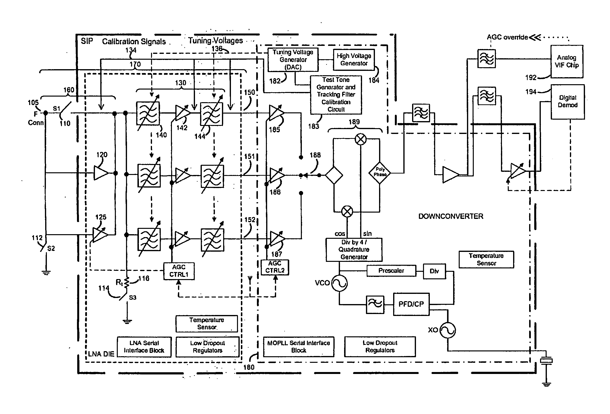
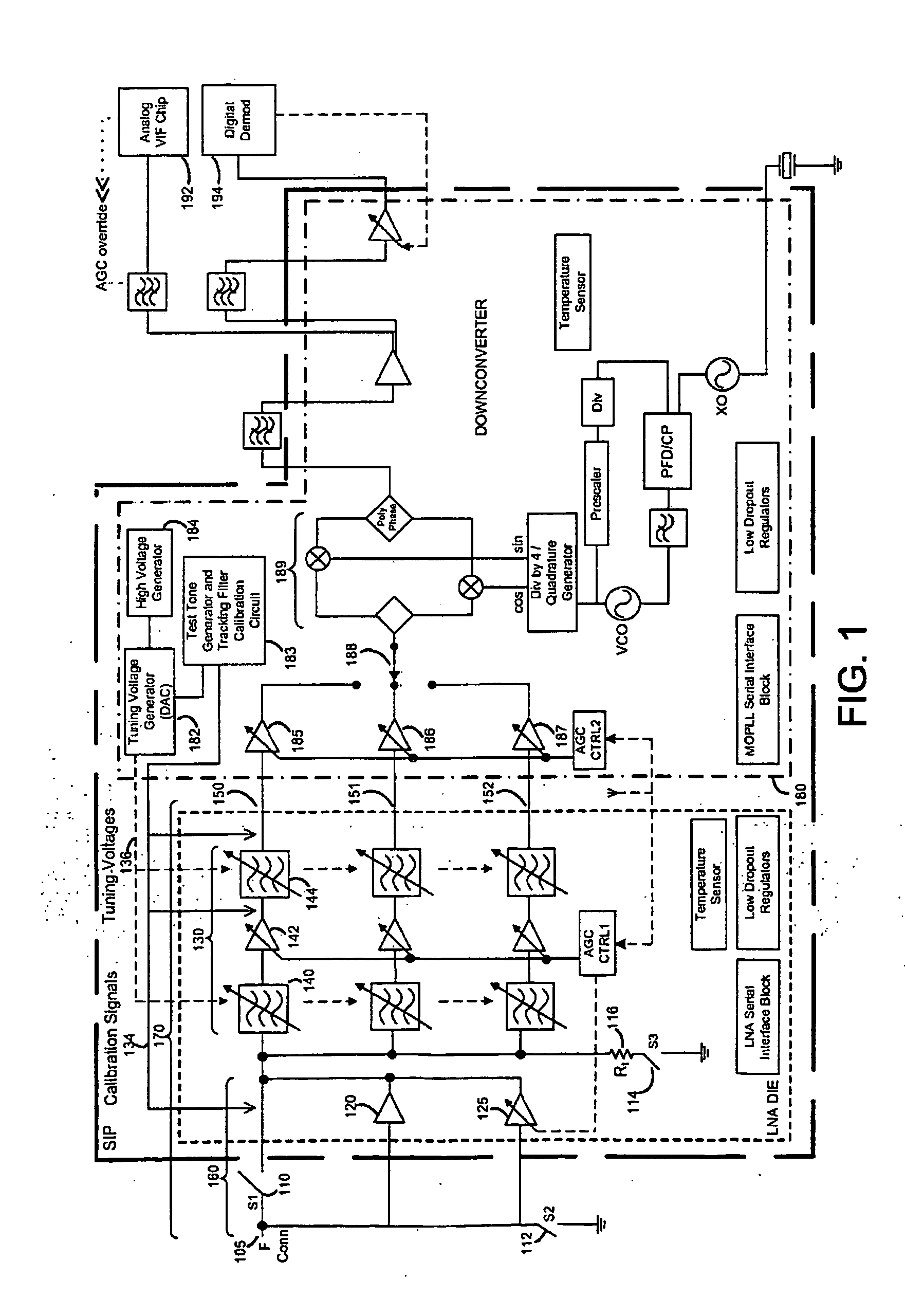
[0047]FIG. 1 shows an example of an implementation of a tuner front-end 170. The tuner front-end 170 includes multi-mode low noise amplifier 160 and tracking filter 130. Tracking filter 130 includes a first stage tracking filter 140, a Low Noise Amplifier (LNA) 142, followed by a second stage tracking filter 144 for desired selectivity. Although other filter line-up architectures known in the art are applicable, this example topology results in a lower noise figure (NF) by reducing the pass band losses with the first stage tracking filter 140 before the signal is amplified by the LNA 142. A single LC (inductor-capacitor) tank can be used in the first stage tracking filter 140 (i.e. one inductor and one or several capacitors). Because the LNA 142 receives a signal that has been band limited by the first stage tracking filter 140, the power handling requirement is reduced relative to a broader band LNA and therefore, the linearity is improved, resulting in less distortion. To further ...


PUM


Abstract

A broadband tuner includes a tracking filter with calibration to compensate for component errors and drift. The filters use off-die inductors that are preferably within a system-in-package (SIP) with other critical tuner components, which produces a highly integrated tuner front end with high Q filters within a single package. High voltage varactors with a large tuning range can be used for variable capacitors. The integration of the tuner into a SIP allows the tuner design to be optimized for cost and performance while keeping the critical RF layout requirements within the tuner. A configurable tuner front end enables modes for low noise, high linearity, good input return loss (S11) across the entire RF band, and applying a test tone in the calibration mode. The switchable mode enables the tuner to be effective during weak terrestrial reception, strong terrestrial reception, and connection to a cable plant.

Description

RELATED APPLICATIONS[0001]This application claims priority from U.S. provisional application No. 60 / 792,539 filed Apr. 17, 2006 entitled “Receiver system with adjustable selectivity”, and U.S. provisional application No. 60 / 792,593 filed Apr. 17, 2006 entitled “Multi-mode low noise amplifier”, each incorporated herein by reference.BACKGROUND[0002]1. Field of Invention[0003]The present invention relates to communication systems and more specifically to an architecture and tracking filters for use in a broadband tuner.[0004]2. Prior Art[0005]Tuners are used for both terrestrial and cable reception within TVs, VCRs, DVD recorders, set-top-boxes, FM radios, modems and other similar consumer devices. The tuner selects a narrowband signal from within a wide- or broad-band signal comprising many channels. The tuner comprises a combination of band pass filtering and frequency down conversion. One known tuner architecture employs a tunable band pass filter, also called a tracking filter, on ...

Claims


Application Information

Patent Timeline
IPC IPC(8): H03J3/20
CPCH03J3/08H03J2200/18H03J2200/08
Inventor SHAH, PETERFRANSIS, BERTBARGROFF, KEITH
Owner ENTROPIC COMM INC
Why Eureka
Try Eureka