[0011]In another embodiment of the present invention, the support device is in the form of an improved soil nail including a fiberglass body and a
metal tip. The
metal tip is preferably made from a single piece of
metal, such as a machined
ingot of
hardened steel. The tip comprises a contacting portion or
stinger that makes contact with the ground when emplaced, and a proximal base portion that is received within an opening in the distal end of the fiberglass body thus allowing the tip to be attached to the fiberglass body. The base portion may be attached by a compression fit within the opening of the body and / or may be secured by an appropriate bonding agent, such urethane glue. The size and dimensions of the soil nail can be modified for the intended purpose of use. One common size acceptable for use in many
soil stabilization efforts includes a fiberglass body of twenty feet in length and a contacting portion of the metal tip extending approximately six inches in length from the distal end of the fiberglass body. For those applications in which a shorter body is required, the same tip construction can be used, and the length of the body can simply be shortened. Unlike most prior art soil nails, the soil nail of the present invention has a tubular shaped body without projections which allows the soil nail to be emplaced by the soil nail launcher disclosed in the U.S. Pat. No. 5,044,831. The use of a soil nail with a fiberglass body in conjunction with a metal tip provides many advantages. The fiberglass body provides a more cost
effective solution than traditional soil nails that are just made of metal. The fiberglass body also is highly resistant to
corrosion, even more so than many metal soil nails within
corrosion treated surfaces. The weight of the soil nail of the present invention is also less than a metal soil nail, allowing it to achieve greater velocity when emplaced by a soil nail launcher, thus enhancing its ability to penetrate the ground. The strength of the soil nail is not compromised because the fiberglass has adequate strength, and has a greater elastic limit as compared to many metal soil nails enabling the nail to
handle even greater tensile and shear loads. Although the soil nail has a relatively smooth outer surface allowing it to be emplaced by a launcher, the surface characteristics of the fiberglass provide excellent adhesion with soil. Additionally, the
stinger can be especially designed to
handle particular soil or rock formations without having to modify the body of the soil nail. For example, in more dense soil or rock formations, the
stinger shape can be modified prior to
assembly with the body thus making the soil nail more adaptable for many uses.
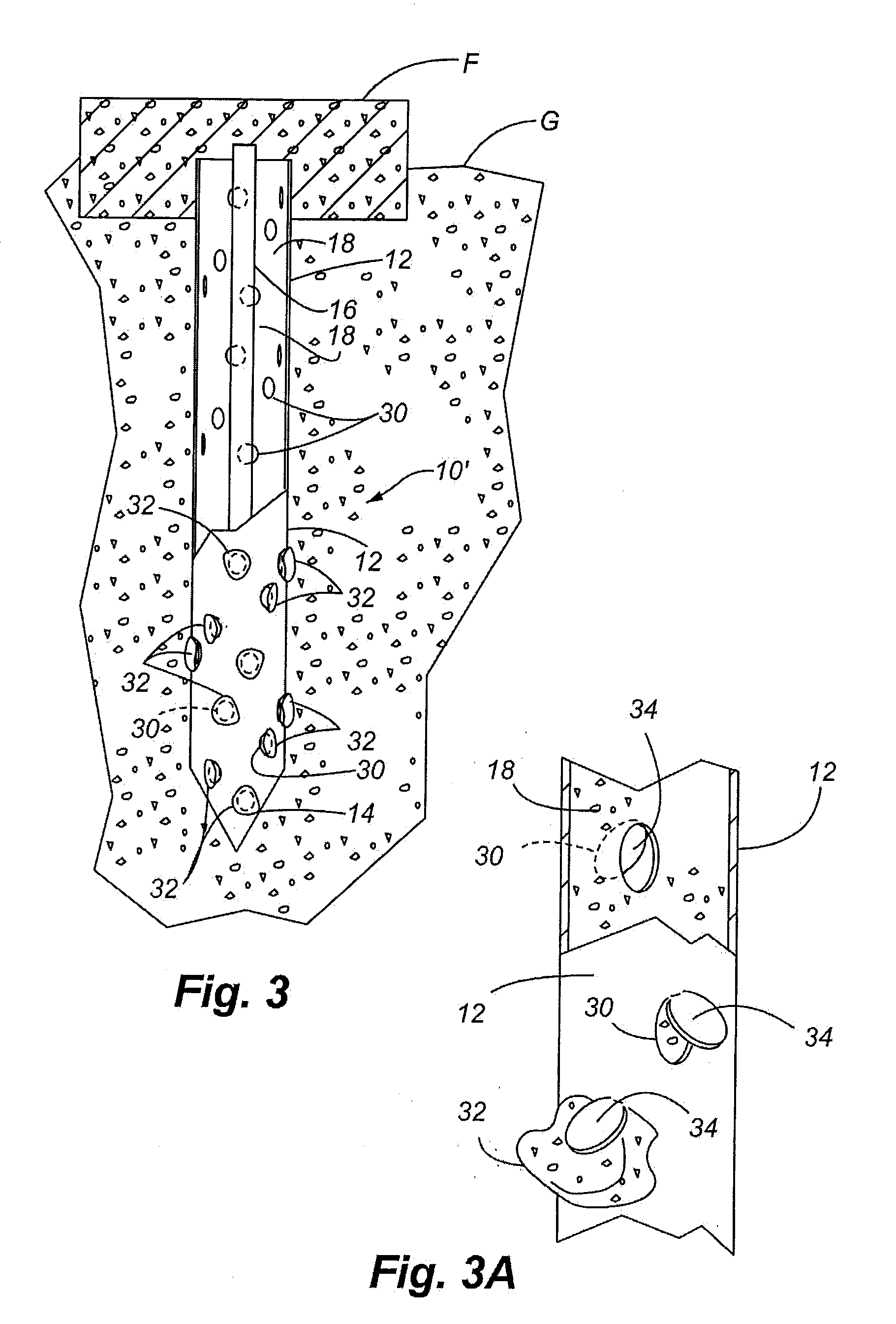
[0012]In another preferred embodiment of the present invention, a self-centralizing soil nail is provided. This self-centralizing feature enables the inner member or inner bar to be centralized within the outer member. The inner member maintains a uniform concentric relationship wherein the inner member is uniformly spaced from the inner surface of the outer member. This feature is achieved by crimping the outer member at selected locations along the length of the outer member thereby narrowing the inner
diameter of the outer member, but maintaining an opening in the outer member large enough for passage of the inner member. The outer member is crimped so that the inner member is centered in the opening of the outer member and, the space between the outer surface of the inner member and the interior surface of the outer member is substantially uniform. Placing the inner member in this centralized relationship increases the capacity of the soil nail both in tension and compression. If the soil nail is not centered and makes contact with the interior surface of the outer member, the inner member is subject to corrosion. Additionally, if the inner member is spaced too closely to the interior surface of the outer member, there may be small voids or spaces that do not completely fill with cementious material and / or the cementious may have a very small thickness which is more susceptible to being fractured. The narrowing of the
diameter of the outer member achieves natural centering of the inner member without having to make an outer member of a more complex construction.
[0015]In yet another preferred embodiment of the present invention, a composite self-drilling soil nail is provided in which the soil nail is installed by drilling. The soil nail is self-installing by inclusion of a
drill tip attached to the distal end thereof. This soil nail more specifically comprises an outer member or tubular member having a threaded outer surface with a hollow opening or bore extending therethrough, and the hollow bore also being threaded. Preferably, the outer member is made of a material such as fiberglass. If it is necessary to extend a length of the outer member, an outer coupler may be used to join the distal end of one outer member with proximal end of an abutting outer member. The outer coupler is a tubular member itself, having internal threads which are threaded in an engagement with the abutting ends of the outer members. A threaded inner member is placed through the threaded bore of the outer tubular member by threaded engagement between threads on the inner bore and external threads on the outer surface of the inner member. As mentioned, the
drill tip is secured to the most distal end of the soil nail enabling the soil nail to be self-drilled. The proximal end of the soil nail receives a bearing plate sized to hold or bear against the specific
geological formation being held by the soil nail. An outer nut is threaded over the outer member and in engagement against the bearing plate. An inner nut is threaded over the inner member that has an end protruding beyond the adjacent end of the outer member, and the inner nut is tightened against the outer nut. The use of the threaded inner member enhances the strength of the soil nail, particularly when using fiberglass as the outer member, and also when fiberglass sections are to be joined for extending a length of the soil nail. The use of steel couplers improves the strength of the joint between the outer members; however, metallic couplers will corrode over time. The use of the inner member provides more permanent tensile and compressive capacity to the overall soil nail, and also helps to compensate for weakening of the metallic coupler over time. If fiberglass couplers are used, the joint between the outer tubular members is relatively weak, but the inner bar again greatly enhances the
bearing capacity of the soil nail. The use of two holding nuts as opposed to a single nut against the bearing plate further provides strength to the
system.
[0017]In another aspect of the invention, various embodiments are provided with surface irregularities or asperities that increase the pull-out capacity of the soil nail. In one embodiment, the surface asperities include protrusions formed on the outer surface of the soil nail. In another embodiment, the surface asperities may include indentations. These surface asperities may be used in combinations. In another aspect, the surface asperities are created by a
galvanization process in which the outer tube or member is subjected to a hot dip galvanizing process. The
molten metal that is to be applied to the outer member is stirred in order to suspend particles in the
molten metal. These particles are referred to as
dross. More specifically,
dross is the
mass of
solid impurities that may float on the surface of the
molten metal, or may be a heavier
impurity that can sink to the bottom of the container holding the
molten material. These impurities are usually removed by skimming the surface or screening the
molten material before the object is subjected to the
hot dip galvanization. In the present invention, these stirred particles within the molten metal provide a beneficial purpose in the creation of a very rough layer of material applied to the outer member. This roughness increases the pull-out capacity, as well as to provide an increased capability for the tube to bond to cementious material placed within the outer member. Therefore, the particles that are normally skimmed from the surface of the molten metal provide a very useful purpose with respect to treating the surface of the outer members.

