Steam turbine blade and method for manufacturing the same

a technology manufacturing methods, which is applied in the direction of wind turbines with perpendicular air flow, machines/engines, heat inorganic powder coating, etc., can solve the problems of increasing manufacturing costs, deterioration of initial turbine performance, and deterioration of the efficiency of the entire turbine, so as to reduce the manufacturing cost and improve the corrosion resistance of steam turbine blades.

Inactive Publication Date: 2010-07-01
KK TOSHIBA
View PDF9 Cites 18 Cited by
  • Summary
  • Abstract
  • Description
  • Claims
  • Application Information

AI Technical Summary

Benefits of technology

[0022]It is an object of the present invention, in light of the conventional problems, to provide a steam turbine blade and a method for manufacturing the same whereby the corrosion-resistance of the steam turbine blade can be enhance...

Problems solved by technology

Such a problem is pointed out as the rotor blades and the stator blades can exhibit excellent aerodynamic characteristics at the initial stage because the surface roughness of the rotor blades and the stator blades is small, but cannot exhibit the excellent aerodynamic characteristics with the operation period of time because the surfaces of the rotor blades and the stator blades are oxidized gradually to coarsen the surface roughness of the rotor blades and the stator blades...

Method used


Image

  • Steam turbine blade and method for manufacturing the same
  • Steam turbine blade and method for manufacturing the same
  • Steam turbine blade and method for manufacturing the same

Examples


example 1

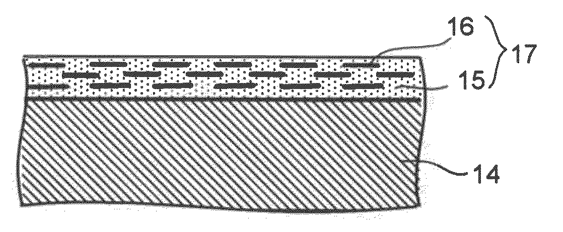
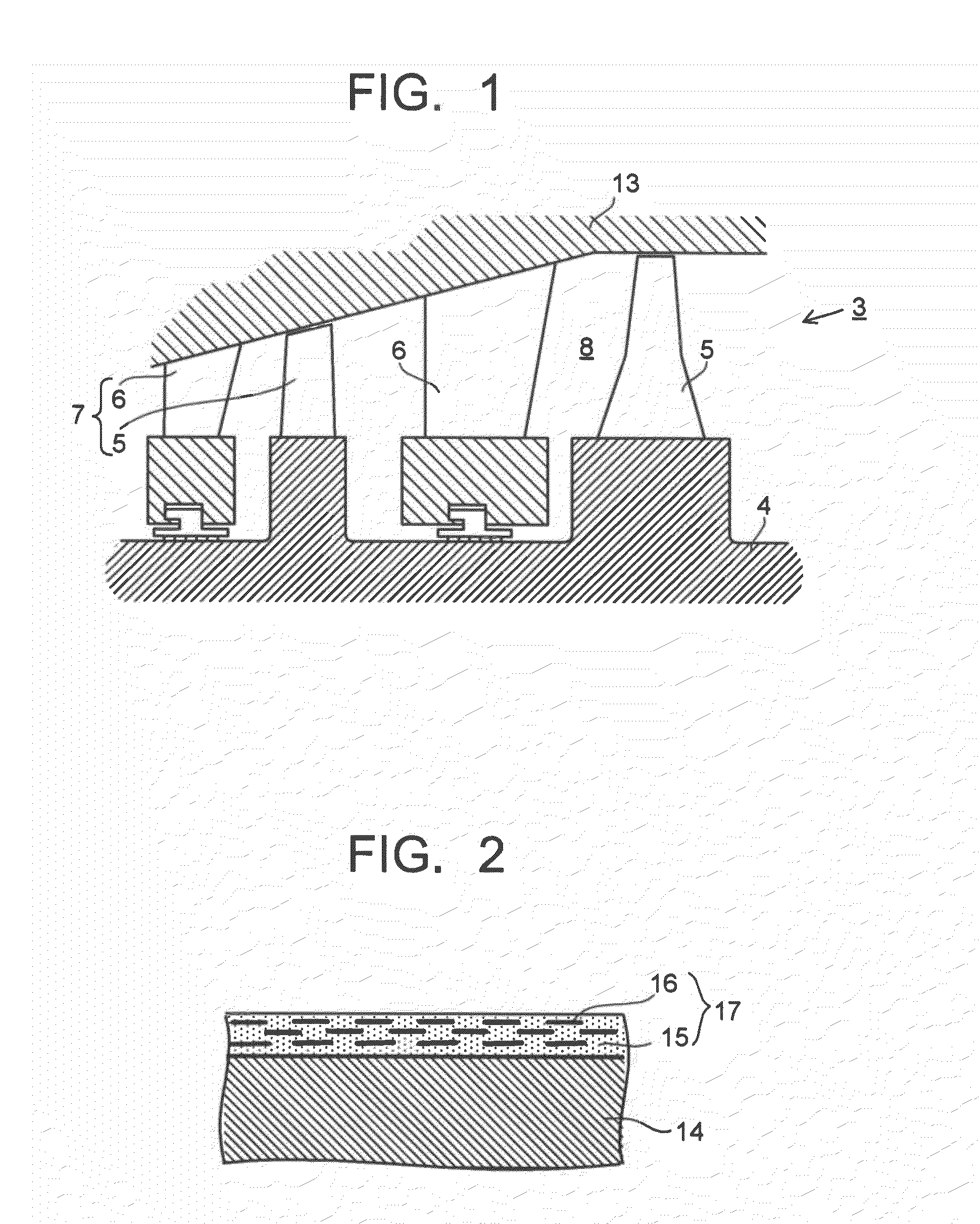
[0051]In this example, silicon oxide nanosheet particles, each having a lateral size of about 1 μm and a thickness of about 1 nm, were added into about 7 wt % zirconium acetate containing water solution. The amount of the nanosheet particles added into the water solution is set such that the amount of the zirconium oxide in the intended coating film was set to 70 vol % for all of the coating film after thermal treatment and the amount of the silicon oxide nanosheet particles was set to 30 vol % for all of the coating film after the thermal treatment. The thus obtained mixed solution was blended using a magnet stirrer and Teflon (registered trademark) rotator to form a slurry solution for coating. The thus obtained coating slurry was coated onto a high-chrome steel plate with a size of 50 mm×50 mm×1 mm by means of dipping, dried at room temperature for about one hour and heated at 300° C. for 5 minutes under atmosphere, thereby forming the intended coating film.

[0052]The thickness of...

example 2

[0054]In this example, the intended coating film was formed in the same manner as Example 1 except that the amount of the silicon oxide nanosheet particles to be added into the slurry solution was decreased to 10 vol % for all of the coating film to be formed. Moreover, the oxidation-resistance test was also carried out in the same manner as Example 1. As a result, the weight change and surface roughness change of the coating film was not almost recognized.

example 3

[0055]In this example, the intended coating film was formed in the same manner as Example 1 except that the amount of the silicon oxide nanosheet particles to be added into the slurry solution was increased to 80 vol % for all of the coating film to be formed. Moreover, the oxidation-resistance test was also carried out in the same manner as Example 1. As a result, the weight change and surface roughness change of the coating film was not almost recognized.


PUM

PropertyMeasurementUnit
Temperatureaaaaaaaaaa
Thicknessaaaaaaaaaa
Thicknessaaaaaaaaaa

Abstract

A steam turbine blade includes a coating film formed at least a portion of a surface of the steam turbine blade, the coating film containing a ceramic matrix and nanosheet particles dispersed in the ceramic matrix. The steam turbine blade is employed as one of stator blades or one of rotor blades in a steam turbine. The steam turbine includes a turbine rotor, the rotor blades implanted in the turbine rotor, the stator blades provided in an upstream side of the corresponding rotor blades, and a turbine casing supporting the stator blades and accommodating turbine rotor, the rotor blades and the stator blades. The steam turbine is also configured such that the rotor blades are paired with the corresponding stator blades to form turbine stages arranged in an axial direction of the turbine rotor, thereby forming steam paths.

Description

CROSS-REFERENCE TO RELATED APPLICATIONS[0001]This application is based upon and claims the benefit of priority from the prior Japanese Patent Applications No. 2008-335313 filed on Dec. 26, 2008 and No. 2009-248559 filed on Oct. 29, 2009; the entire contents which are incorporated herein by reference.BACKGROUND[0002]1. Field of the Invention[0003]The present invention relates to a steam turbine blade and a method for manufacturing the steam turbine blade, particularly which can maintain and develop the aerodynamic characteristics of the rotor blades (blades) and the stator blades (nozzles) composing the steam turbine and thus the performance of the steam turbine.[0004]2. Background of the Invention[0005]In a steam turbine, the pressure and high temperature energy of the high temperature and high pressure steam supplied from the boiler is converted into the corresponding rotational energy using the turbine cascade of the rotor blades and the stator blades. FIG. 3 is a conceptual view ...

Claims


Application Information

Patent Timeline
IPC IPC(8): F01D9/02F01D5/28B05D3/02
CPCC23C24/00C23C24/08F01D5/284F01D5/288F05D2230/90F05D2300/2118F05D2300/211F05D2300/2112
Inventor SAYANO, AKIOTAKAHASHI, MASASHISAITO, MASAHIRONAKAJIMA, KAZUYOSHIHUANG, JIANSHUNMORI, KAZUHIKO
Owner KK TOSHIBA
Why Eureka
Try Eureka