Nanoparticles, conductive ink and circuit line forming device

a technology of conductive ink and circuit line, which is applied in the direction of conductors, magnetic bodies, applications, etc., can solve the problems of reducing the size of electronic devices, affecting the service life of devices, and reducing the size of or the distance between wires, so as to prevent the phenomenon of coffee staining and migration, and improve the reliability of electrical devices

Inactive Publication Date: 2010-07-08
SAMSUNG ELECTRO MECHANICS CO LTD
View PDF6 Cites 23 Cited by
  • Summary
  • Abstract
  • Description
  • Claims
  • Application Information

AI Technical Summary

Benefits of technology

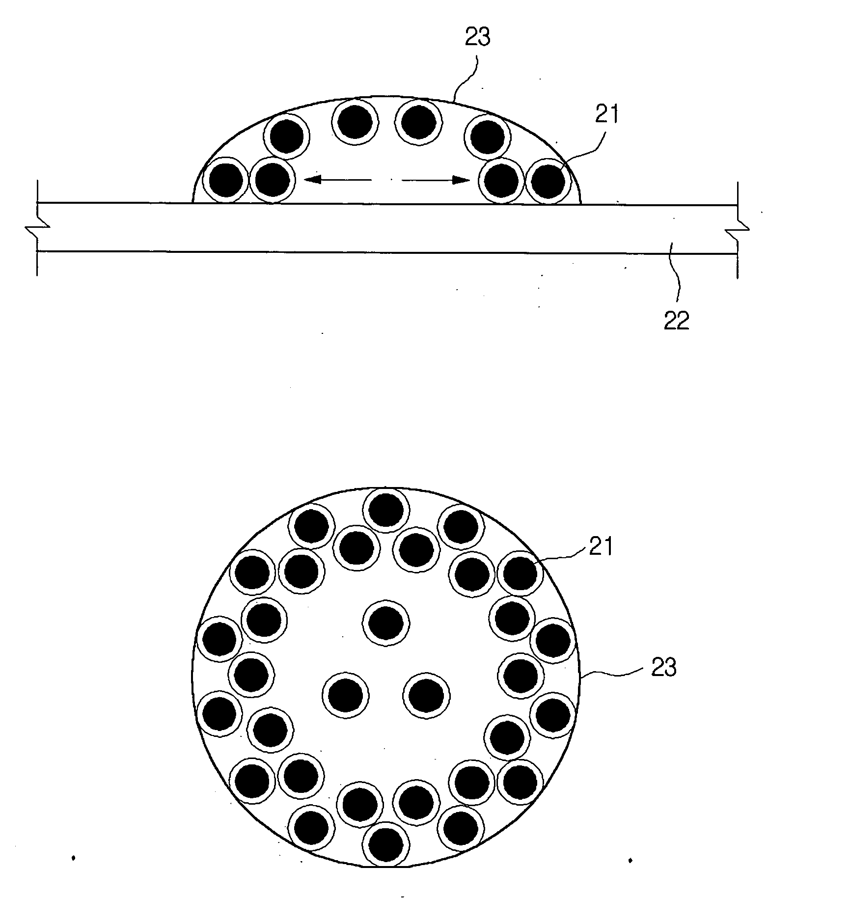
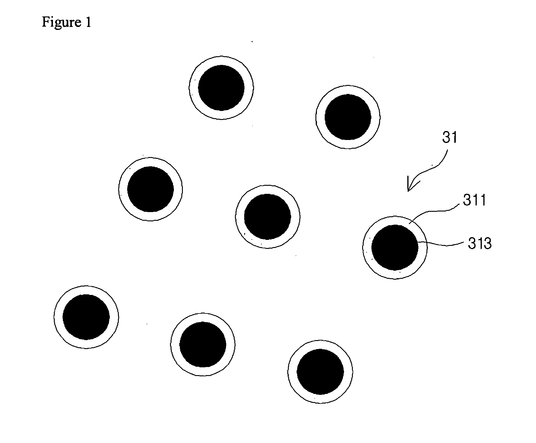
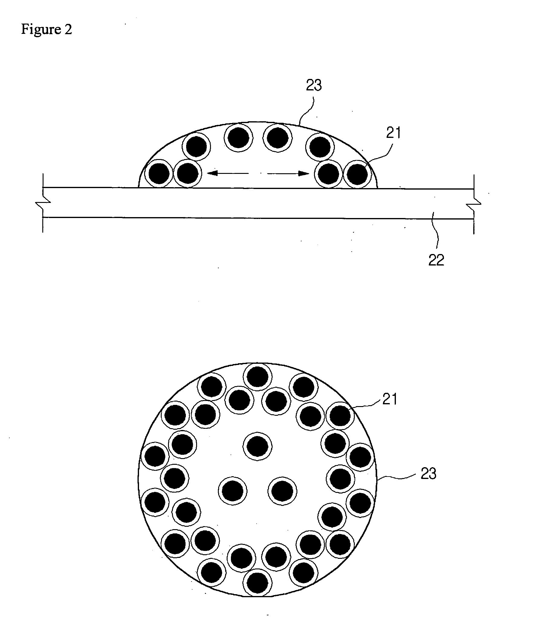
[0008]Aspects of the present invention provide ferromagnetic nanoparticles having a core-shell structure. Also, conductive ink containing such ferromagnetic nanoparticles is provided. Aspects of the invention also provide a circuit line forming device which forms micro circuit lines with such ferromagnetic conductive ink using a magnetic field. Also, aspects of the invention provide a circuit line forming device allowing superior electrical reliability by uniformly distributing nanoparticles in the ejected ink to prevent the coffee stain phenomenon and migration.

Problems solved by technology

However, with the continued decrease in the size of electronic devices, there is a demand for even more microscopic circuit lines.
However, satisfying the size of or the distance between wires required by the trend towards lighter and smaller devices is hindered by the problem of resolution in printing technology.
Resolution depends on the diameter of the ink droplets ejected from the inkjet head and the surface tension and interfacial tension of the ink, but there is a limit to decreasing the size of the inkjet head or the diameter of the ejected droplets due to problems such as having to include metal nanoparticles for forming conductive circuit lines.
When ejecting ink by the inkjet technique, the problem of dispersion on the substrate is also an obstacle to forming micro circuit lines.
This causes a conductive or metallic migration phenomenon to consequently affect the reliability of the product.

Method used


Image

  • Nanoparticles, conductive ink and circuit line forming device
  • Nanoparticles, conductive ink and circuit line forming device
  • Nanoparticles, conductive ink and circuit line forming device

Examples


example 1

(1) Synthesis of Cores Containing Fe

[0041]0.63 g of FeCl2 and 6 g of cetyltrimethylammonium bromide were dissolved in 20 ml of H2O, 10 g of 1-penthanol, and 30 g of hexane. Here, a reducing solution was added of 0.37 g of NaBH4 dissolved in 10 ml of H2O, and the solution was stirred for 2 hours. After the stirring, the synthesized nanoparticles were separated from the solvent using a magnet and cleansed with methanol. The cleansed Fe nanoparticles were dried in a 50° C. vacuum oven.

(2) Synthesis of Fe / Ag Nanoparticles

[0042]The Fe nanoparticles formed in step (1) were dissolved, together with 0.75 g of AgNO3 and 3 g of cetyltrimethylammonium bromide, in 20 ml of H2O, 20 g of 1-penthanol, and 40 g of hexane. Here, a reducing solution was added of 0.11 g of dissolved NaBH4, and the solution was stirred for 12 hours. After the stirring, the synthesized nanoparticles were separated from the solvent using a magnet and cleansed with methanol. The cleansed Fe nanoparticles were dried in a 5...

example 2

(1) Synthesis of Cores Containing Fe

[0043]4 mmol of Fe alkanoate was dispersed in 50 ml of 1-octadecane, and the temperature of the solution was increased at 5° C. per minute to 310° C., to reflux the solution for 30 minutes. Afterwards, the solution was cooled to normal temperature, and 150 ml of alcohol was added to precipitate Fe nanoparticles. The precipitated Fe nanoparticles were retrieved using a ferromagnet and were cleansed twice or more with a mixed solution of alcohol and acetone before drying. Here, the Fe nanoparticles may also be obtained using a hydrocarbon solvent, such as toluene, xylene, and 1-hexadecane, instead of 1-octadecane.

(2) Synthesis of Fe / Ag Nanoparticles

[0044]Ag alkanoate was dissolved in 1-octadecane in a mole ratio of 2:1 with respect to the Fe nanoparticles synthesized in step (1), after which pyrolysis, cleansing, and drying were performed on the solution as in step (1) to obtain Fe / Ag nanoparticles of a core-shell structure.

example 3

(1) Synthesis of Cores Containing Co

[0045]4 mmol of Co alkanoate was dispersed in 50 ml of 1-octadecane, and the temperature of the solution was increased at 7° C. per minute to 350° C., to reflux the solution for 30 minutes. Afterwards, the solution was cooled to normal temperature, and 150 ml of alcohol was added to precipitate Co nanoparticles. The precipitated Co nanoparticles were retrieved using a centrifugal separator and cleansed were twice or more with a mixed solution of alcohol and acetone before drying. Here, the Co nanoparticles may also be obtained using a hydrocarbon solvent, such as toluene, xylene, and 1-hexadecane, instead of 1-octadecane.

(2) Synthesis of Co / Au Nanoparticles

[0046]Au alkanoate was dissolved in 1-octadecane in a mole ratio of 2:1 with respect to the Co nanoparticles synthesized in step (1), after which pyrolysis, cleansing, and drying were performed on the solution as in step (1) to obtain Co / Au nanoparticles of a core-shell structure.


PUM

PropertyMeasurementUnit
sizeaaaaaaaaaa
temperatureaaaaaaaaaa
mole ratioaaaaaaaaaa

Abstract

A nanoparticle for conductive ink including a ferromagnetic core and a conductive layer surrounding the ferromagnetic core. The ferromagnetic core is 5 to 40 parts by weight, per 100 parts by weight of the nanoparticles. The conductive ink provides electrical reliability by allowing a uniform distribution of nanoparticles in ejected ink and prevents the coffee stain phenomenon and migration.

Description

BACKGROUND[0001]1. Technical Field[0002]The present invention relates to nanoparticles, conductive ink containing the nanoparticles, and a circuit line forming device using the conductive ink, and in particular, to nanoparticles, conductive ink, and a circuit line forming device for forming micro circuit lines.[0003]2. Description of the Related Art[0004]A method has recently been proposed of forming micro circuit lines on a substrate by the inkjet technique. This method allows selective forming of micro circuit lines to provide benefits in terms of time and economy. However, with the continued decrease in the size of electronic devices, there is a demand for even more microscopic circuit lines. However, satisfying the size of or the distance between wires required by the trend towards lighter and smaller devices is hindered by the problem of resolution in printing technology. Resolution depends on the diameter of the ink droplets ejected from the inkjet head and the surface tension...

Claims


Application Information

Patent Timeline
Patent Type & Authority Applications(United States)
IPC IPC(8): H01F1/04B22F1/054B22F1/17B22F9/24B82Y30/00B82Y40/00B82Y99/00C09D11/02C09D11/03C09D11/52C23C26/00H01B1/22H01B5/00
CPCB22F1/025B22F9/24C09D11/52H01B1/02H01B1/16H05K1/097H05K2201/0218H05K2201/083B22F1/0018Y10S977/775B82Y30/00Y10T428/2991B22F1/054B22F1/17B82B1/00H01B1/22
Inventor SHIM, IN-KEUNJOUNG, JAE-WOO
Owner SAMSUNG ELECTRO MECHANICS CO LTD
Why Eureka
Try Eureka