Oriented polymer implantable device and process for making same

Inactive Publication Date: 2010-07-29
KENSEY NASH CORP
View PDF41 Cites 873 Cited by
  • Summary
  • Abstract
  • Description
  • Claims
  • Application Information

AI Technical Summary

Benefits of technology

[0030]The non-continuous or discontinuous processing of the polymer leads to a reduction in cross-section as it is processed, thereby creating orientation of the polymer, and the resul

Problems solved by technology

A further disadvantage of metallic hardware is it is often necessary to perform another operation to remove the metal implants after the bone has healed.
These processes result in a material having a relaxed orientation or molecular arrangement of the polymer as it cools, and typically does not impart great strength values, such as those required for tissue and/or bone fixation treatments suitable for implantation through surgical techniques (e.g., orthopedic applications).
In order to yield the appropriate strength, the size of the implants must be increased which can lead to cosmetic issues (bulges, specifically with maxillofacial plates), anatomical interference issues (such as dysphagia with anterior cervical spine plates or tendon irritation with distal radius plates), and an increase in degradation mass which can cause adverse biological reactions as the polymer is resorbed.
Should the polymer implant, without being heated above glass transition, be bent beyond its elastic limit, the polymer will typically fracture upon being bent to the degree often necessary for shaping orthopedic fixation plates for application.
Machining a desired shape from a generic slug or billet often results in excessive waste, as the amount of material that is trimmed or cut off in making the final product will be much greater than the amount removed during final machining of a molded or formed polymer material that is shaped nearly to final form.
This extensive machining creates a great amount of chips or cut dust as waste of the material that is machined off.
Excessive waste of raw material is especially problematic in devices constructed of relatively expensive polymers, such as bioabsorbable polymers and medical grade polymers, as costs are elevated due to the loss of the mater

Method used


Image

  • Oriented polymer implantable device and process for making same
  • Oriented polymer implantable device and process for making same
  • Oriented polymer implantable device and process for making same

Examples


Example

Example 1

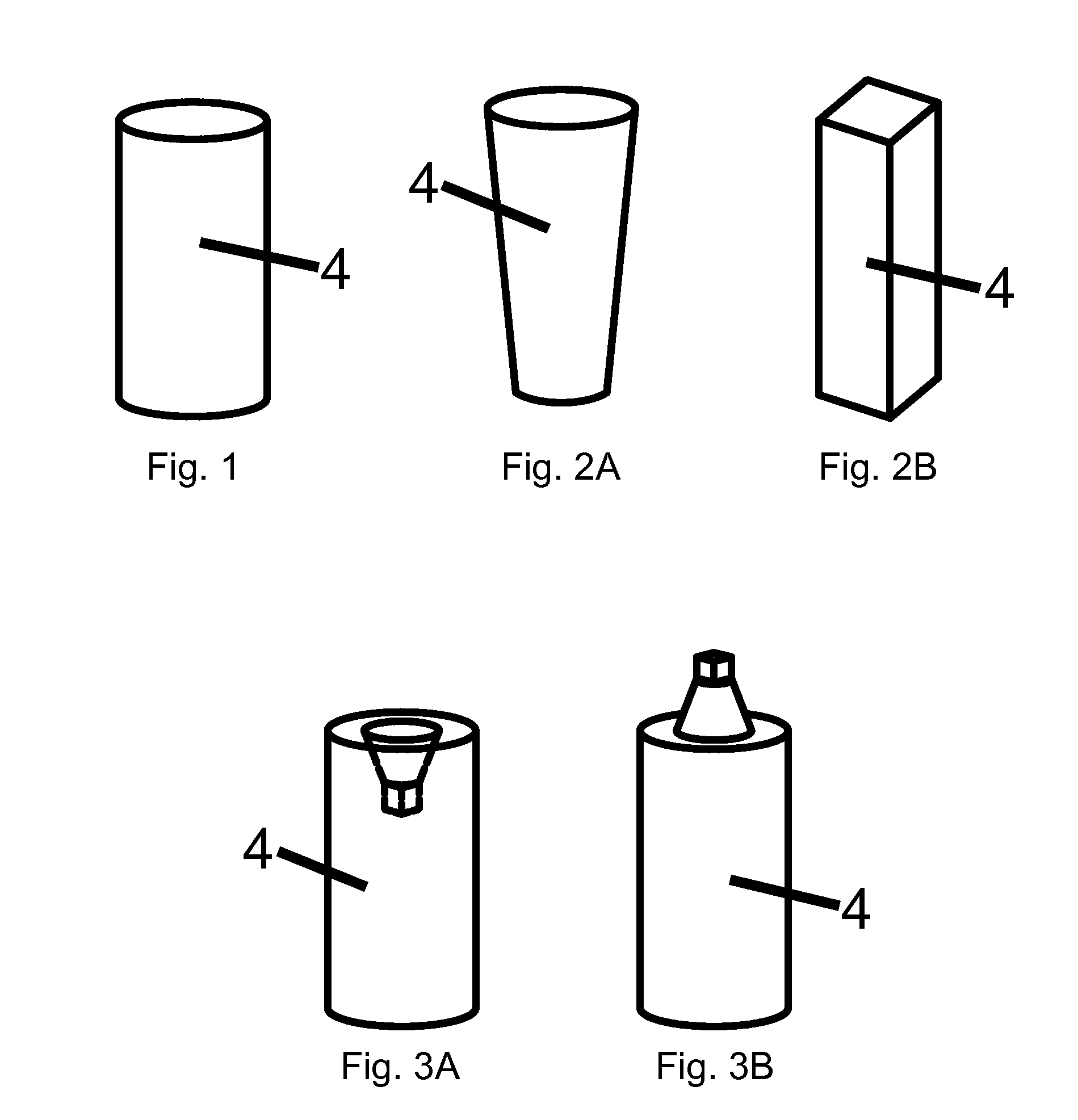
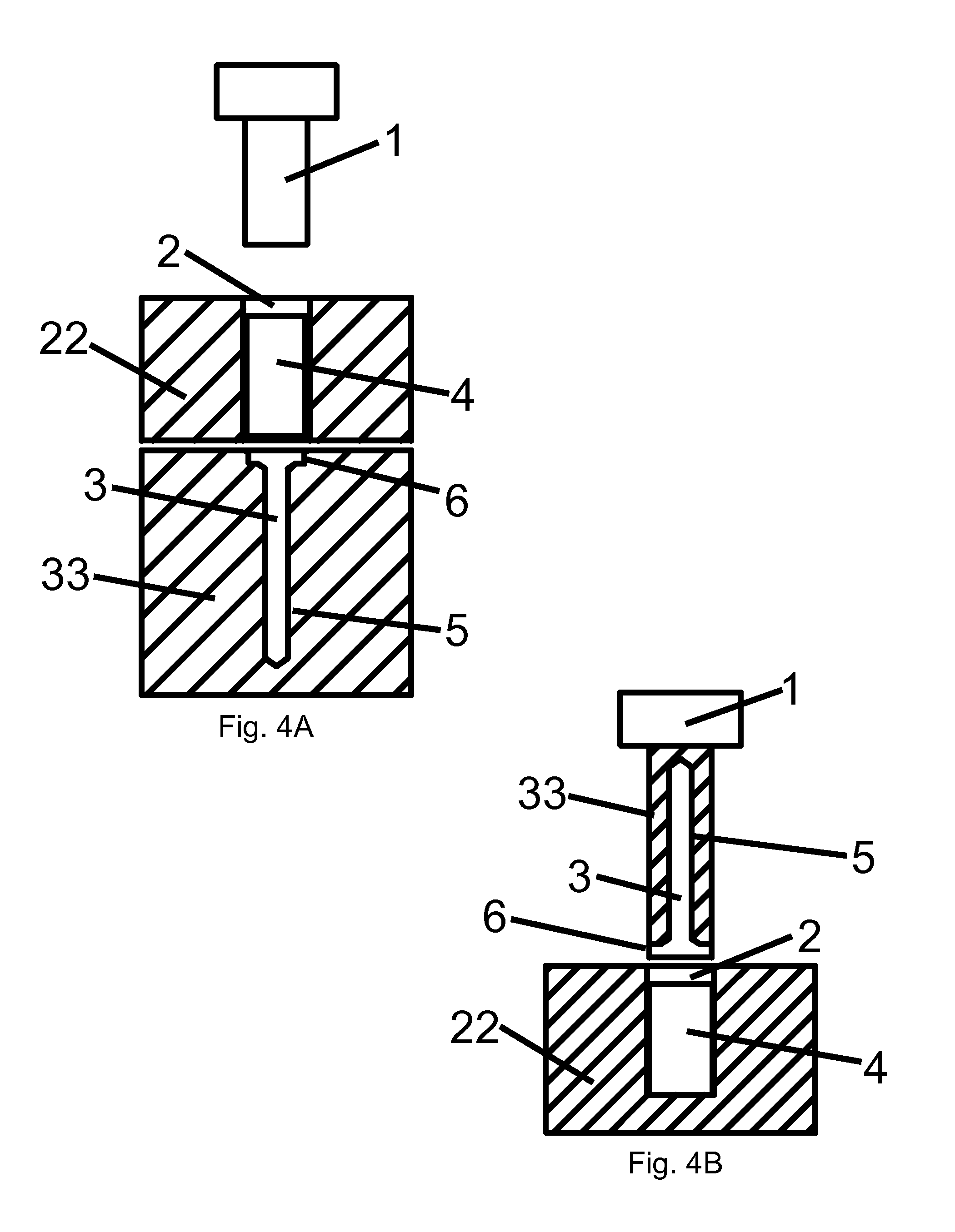
[0098]Rectangular slugs were fabricated by injection molding 85 / 15 poly(L-lactide-co-glycolide). The slugs were placed into a tooling arrangement heated to 96° C. and the polymer heated to a temperature above the Tg of the polymer but below the Tm of the polymer. A ram press was used to apply pressure to the slug and force the material into the die, the die having a smaller cross-section than the slug. A draw ratio of approximately 4:1 was used. The die geometry was such that it formed a straight plate approximately 50×7×2.5 mm (L×W×T). The slug and die were cooled to a temperature sufficient to allow removal of the pressed part. The parts were evaluated to determine their bending ability in hot water (65° C.). Previous trials with high-strength oriented polymer devices made by prior art continuous processes indicated that the material was highly unstable dimensionally when heated above its glass-transition to allow it to be bent. The high-strength, oriented plate of this e...

Example

Example 2

[0099]Rectangular slugs were fabricated by injection molding 85 / 15 poly(L-lactide-co-glycolide). The slugs were placed into a tooling arrangement heated to 110° C. and the polymer heated to a temperature above the Tg of the polymer but below the Tm of the polymer. A ram press was used to apply pressure to the slug and force the material into the die, the die having a smaller cross-section than the slug. A draw ratio of approximately 4:1 was used. The die geometry was such that it caused the material to curve at an angle creating a bent-axis L-plate. The slug and die were cooled to a temperature sufficient to allow removal of the pressed part. The parts were evaluated to determine their bending ability and L-plate geometry retention in hot water (65° C.). This temperature is well in excess of the polymer's Tg. The high-strength, oriented L-plate was found to be much easier to bend when heated and it was found that the material maintained its thickness and length, as well as ...

Example

Example 3

[0100]Circular slugs were fabricated by extruding poly(L-lactide) rod and then cutting the rod to length using standard machining techniques. The slugs were placed into a tooling arrangement heated to 159° C. and the polymer heated to a temperature above the Tg of the polymer but below the Tm of the polymer. A ram press was used to apply pressure to the slug and force the material into the die, the die having a smaller cross-section than the slug. A draw ratio of approximately 4:1 was used. The die geometry was such that it formed a pin approximately 3.5×40 mm (Diameter × Length). The slug and die were cooled to a temperature sufficient to allow removal of the pressed part. The parts were evaluated to determine their dimensional and strength stability after heating in hot water (70° C.). This temperature is well in excess of the polymer's Tg. The parts were measured before and after immersion in hot water for 1 hour. An ANOVA analysis was performed and it was determined tha...


PUM

PropertyMeasurementUnit
Temperatureaaaaaaaaaa
Dimensional stabilityaaaaaaaaaa
Strengthaaaaaaaaaa

Abstract

A device is formed by a discontinuous process into a bone screw, plate, or fastener, wherein the device has a degree of polymer alignment and strength, and upon reheating above glass transition temperature of the polymer, the device remains dimensionally stable, as it maintains its dimensions, strength, and degree of polymer orientation. In practice of the present invention, the polymer slug is pressed into the die cavity by the actuation of ram press, causing the slug to conform to the die cavity.

Description

CROSS-REFERENCE TO RELATED APPLICATIONS[0001]This patent document is a Continuation-In-Part of copending and commonly owned U.S. patent application Ser. No. 12 / 119,959, filed on May 13, 2008, which is a Continuation of copending and commonly owned U.S. patent application Ser. No. 10 / 780,159, filed Feb. 17, 2004, in the names of Joseph DeMeo et al. and entitled, “Oriented Polymer Implantable Device and Process For Making Same.” The entire contents of the prior applications are expressly incorporated by reference.BACKGROUND OF THE INVENTION[0002]This application relates generally to medical implant devices and their production, specifically relating to the process of manufacturing a polymer tissue and / or bone fixation device, preferably made of a resorbable polymer. The invention more particularly concerns a method of manufacturing a resorbable bone fixation device (e.g., plate, screw, rod, pin, etc.) by forcing a provided polymer slug or billet into a mold while the polymer is in a g...

Claims


Application Information

Patent Timeline
IPC IPC(8): A61B17/86B29C43/52A61B17/80A61B17/84
CPCA61B17/80A61B17/866A61F2/0811A61L31/06A61L31/14B29C43/003B29C2043/503B29C43/16B29C2043/3634C08L67/04
Inventor DEMEO, JOSEPHHEARN, PATRICK E.MCDADE, ROBERT L.
Owner KENSEY NASH CORP
Why Eureka
Try Eureka