Device and Method For Particle Manipulation in Fluid

a technology of fluid medium and device, applied in the direction of filtration separation, separation process, laboratory glassware, etc., can solve the problems of not being able to recover particles from filters, being highly sensitive to perturbations, and not having widespread technological applications

Inactive Publication Date: 2010-08-05
YEDA RES & DEV CO LTD
View PDF11 Cites 96 Cited by
  • Summary
  • Abstract
  • Description
  • Claims
  • Application Information

AI Technical Summary

Benefits of technology

[0029]According to still further features in the described preferred embodiments the device further comprises a control unit capable of controlling the at least one ultrasound transmission pair to provide ultrasound waves of controlled frequency adapted to the transverse dimensions of the primary microchannel, such as to form the standing wave. According t

Problems solved by technology

Additionally, in such methods particle recovery from the filters used is not possible.
The govern forces of this phenomenon are acoustic forces which are, however, weak compared with, e.g., viscous forces in the

Method used


Image

  • Device and Method For Particle Manipulation in Fluid
  • Device and Method For Particle Manipulation in Fluid
  • Device and Method For Particle Manipulation in Fluid

Examples


example 1

Numerical Simulations

[0112]The present example provides a mathematical model for describing the dynamics of a particle in a channel flow. The equation of motion for a particle in a viscous medium carrying an ultrasonic standing wave can be written as:

mÿ=Fst sin(2ky)−C{dot over (y)},  (EQ. 5)

where m is the particle mass, C=6πηR is the Stokes coefficient, Fst is the amplitude of the ultrasonic force, and y is the coordinate across the channel. The dots above the coordinate y commonly represent a time-derivative, as known in the art. The relation between the ultrasonic force and energy density is given by (see also Equations 1 and 2 above):

Fst=4πkR3ĒstΦ(Λ,σ).  (EQ. 6)

[0113]Equation 5 was solved numerically using the values of Fst=2.5×10⁻⁶ dyn and C=0.94×10⁻⁴ g / s, corresponding to R=5 μm, k=209.4 cm−1, Ēst=35 erg / cm3, Φ=0.22 and η=1 centistoke. As stated, the fitting parameter β was introduced to account for energy loses.

[0114]FIG. 6 shows the obtained trajectories of the particles in t...

example 2

Prototype Device

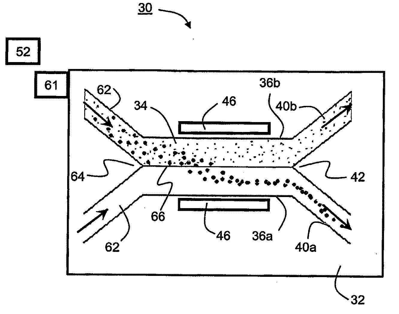
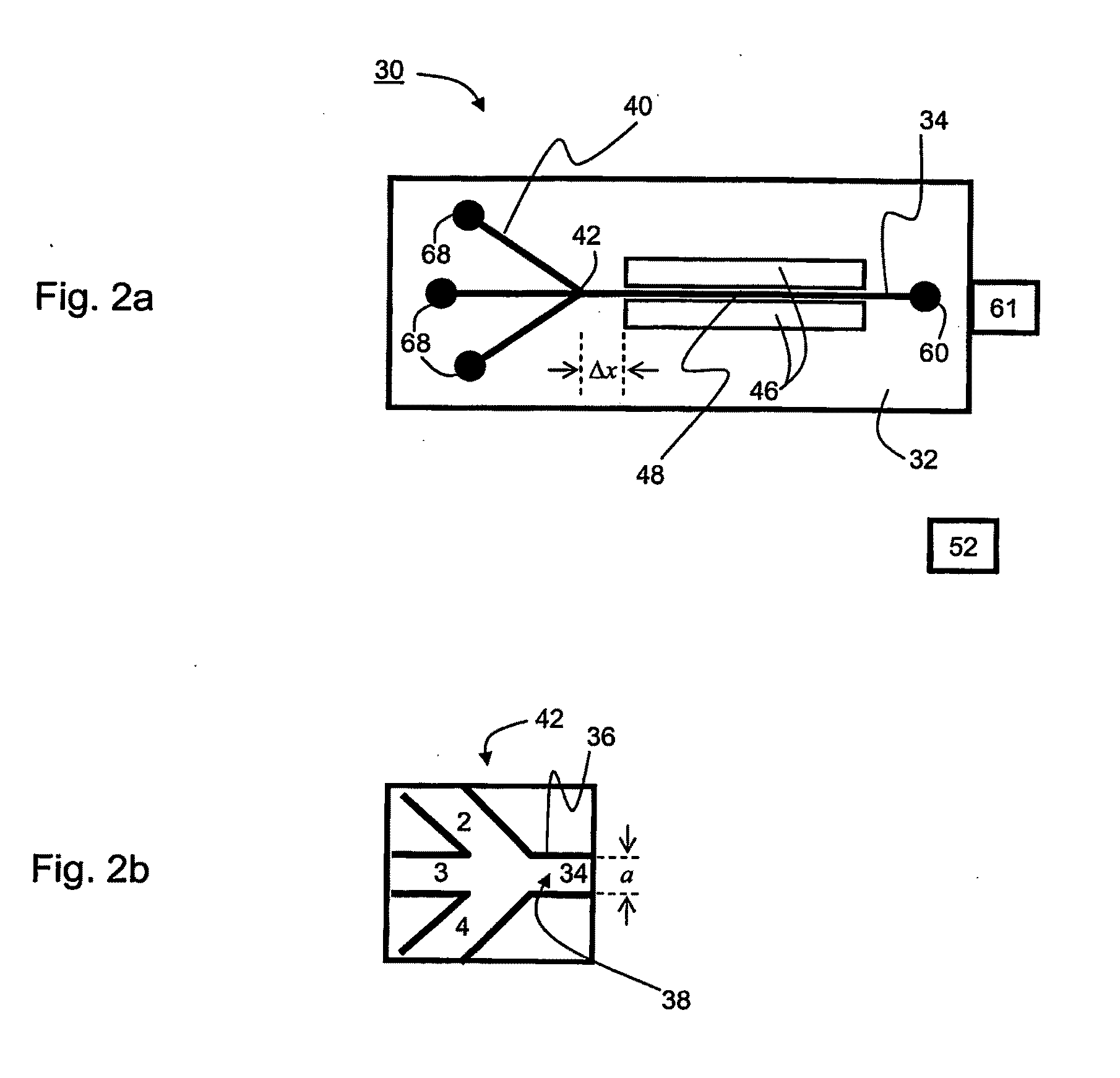
[0120]Prototype devices were manufactured and tested according to various exemplary embodiments of the present invention. Three prototypes designs were manufactured, two for particle separation and one for size sorting. The prototype devices for particle separation are schematically illustrated in FIGS. 2a-b (“one-stage” device) and FIG. 3 (“three-stage” device), and the prototype device for size sorting is schematically illustrated in FIG. 5.

Materials and Methods

[0121]Molds for microchannels were produced by a soft lithography technology using UV-sensitive epoxy (SU-8). A microfluidic chip was made of a silicone elastomer Sylgard 184 (specific gravity 1.05 gr / cm3 at 25° C., linear thermal expansion coefficient is 3·104 cm / cm per ° C.) with curing time of 4 hours at 65° C.

[0122]The cross-sectional dimensions of the microchannel for particle and erythrocytes separation were 160 μm (about half the sound wavelength, λ) in width and 150 μm in depth. The dimensions of the...

experiment 1

Continuous Particle Separation

[0140]Clearance coefficient K(Q) measurements for the 5 μm particles were preceded by measurements of particle trajectories for different initial locations, from which the value of the β parameter (quantifying the correction for the theoretical acoustic energy density) was determined. Good agreement between the measurements and the simulations were obtained for β=0.2 (see FIG. 6 in Example 1 hereinabove).

[0141]FIG. 9 shows the clearance coefficient K(Q) as a function of the fluid discharge obtained experimentally for the 6 different volume concentrations of the 5 μm particles. The results shown in FIG. 9 are generally of the same type as the numerical simulations (see FIG. 7). There are two main reasons for the differences in absolute values of K for the different concentrations. Firstly, the absolute values of K for the 0.33% concentration are smaller then those for higher concentrations up to 7.5% due to casual particles located outside the velocity a...


PUM

PropertyMeasurementUnit
Flow rateaaaaaaaaaa
Sizeaaaaaaaaaa
Widthaaaaaaaaaa

Abstract

A device for manipulating particles present in a fluid medium is disclosed. The device comprises a planar substrate, formed with at least one primary microchannel to allow passage of the fluid medium therethrough. The primary microchannel(s) has walls and a base and being in fluid communication with a plurality of secondary microchannels via at least one branching point. The device further comprises one or more ultrasound transmission pairs, positioned at opposite sides of the walls to generate ultrasound waves propagating through the fluid medium, substantially parallel to the planar substrate, such as to form a standing wave within the primary microchannel.

Description

FIELD AND BACKGROUND OF THE INVENTION[0001]The present invention relates to a device and method for manipulating particles in a fluid medium, and more particularly, to a device and method which employ ultrasound waves for separating and / or sorting particles in a fluid medium.[0002]Increasing needs in biotechnology, environmental science and medical applications in continuous flow analysis require filtration of basic fluids from particles and cells that can interfere with the on-line analysis. Such continuous flow to separators and size sorters are also needed in the fast developing field of micro-fluidics.[0003]Known cell separation methods from body fluids operate by means of filtration, centrifugal force or sedimentation. Traditional methods employ sequential steps for freeing liquids from particles (water processing) and removing the liquid thereafter. Such techniques are typically employed in large scale biotechnological processes, water purifications and particle-flow separator...

Claims


Application Information

Patent Timeline
IPC IPC(8): B03B5/62B01D21/28B01D21/30
CPCB01L3/502761B01L3/502776B01L2200/0636B01L2400/0487B01L2300/0864B01L2400/0439B01L2200/0647
Inventor STEINBERG, VICTORKANTSLER, VASILYMATLIS-STEINBERG, SOPHIEKAPISHNIKOV, SERGEY
Owner YEDA RES & DEV CO LTD
Why Eureka
Try Eureka