Quadrupole mass spectrometer

a quadrupole mass spectrometer and quadrupole technology, applied in mass spectrometers, particle separator tube details, separation processes, etc., can solve the problems of low detection sensitivity for ions having relatively large mass-to-charge ratios, low detection sensitivity, and high detection sensitivity. , the effect of reducing detection sensitivity

Active Publication Date: 2010-08-05
SHIMADZU CORP
View PDF5 Cites 30 Cited by
  • Summary
  • Abstract
  • Description
  • Claims
  • Application Information

AI Technical Summary

Benefits of technology

[0025]In the quadrupole mass spectrometer according to the first aspect of the present invention, the bias voltage information that relates a scan speed at which the mass-to-charge ratio is scanned by the quadrupole mass filter to a DC bias voltage appropriate for the scan speed is stored beforehand, for example in a tabular form, in the memory section. This information can be prepared beforehand by a manufacturer in the course of a tuning process before the product is shipped from the manufacturer. It is also possible to further include a bias voltage information-obtaining section for obtaining the bias voltage information and storing the obtained information in the memory section, the bias voltage information being obtained by performing, for each of a plurality of selectable levels of the scan speed, the operation of monitoring the detection signal produced by the detector while changing the DC bias voltage applied to the quadrupole mass filter, to find a value of the DC bias voltage at which the intensity of the detection signal is maximized.
[0026]In any case, the bias voltage information is already stored in the memory section before the auto-tuning is performed. Accordingly, in the auto-tuning mode, the tuning section uses the bias voltage information to specify a DC bias voltage corresponding to an intended scan speed. Then, it determines a voltage condition that maximizes the intensity of a detection signal produced by the detector under the condition that the specified DC bias voltage is applied to the quadrupole mass filter by the voltage-applying section. The voltage condition is recorded as the auto-tuning result. In this mode of operation, it is preferable to specify the DC bias voltage for each of a plurality of selectable levels of the scan speed and perform the auto-tuning for each level of the scan speed while changing the DC bias voltage applied to the quadrupole mass filter. In an analysis of a target sample, when the scan speed is specified as one of the analysis conditions by an operator, the analysis-performing section performs the analysis of the target sample after determining an appropriate DC bias voltage on the basis of the bias voltage information stored in the memory section and setting the voltage condition determined by the tuning section.
[0027]According to this method, an auto-tuning operation for optimally or almost optimally setting the voltages applied to the relevant sections and other conditions is performed under the condition that an optimal or approximately optimal DC bias voltage for the speed of scanning the ion-selecting voltage is set in the quadrupole mass filter. In the analysis of a target sample, a DC bias voltage appropriate for the scan speed specified by the operator is automatically set. Therefore, the operator can perform the analysis of the sample under an appropriate DC bias voltage without any particular knowledge about the setting of...

Problems solved by technology

Thus, the detection sensitivity deteriorates as the scan speed is raised.
However, the auto-tuning operation performed by the previously described quadrupole mass spectrometer does not include determining an appropriate ion-drawing bias voltage for each scan speed.
Therefore, changing the ion-drawing bias voltage according to the scan speed during the actual analysis of an unknown sample does not always guarantee that the DC electric field within the space between the quadrupole mass filter 3 and the ion optical system 2 is optimized in term...

Method used


Image

  • Quadrupole mass spectrometer
  • Quadrupole mass spectrometer
  • Quadrupole mass spectrometer

Examples


first embodiment

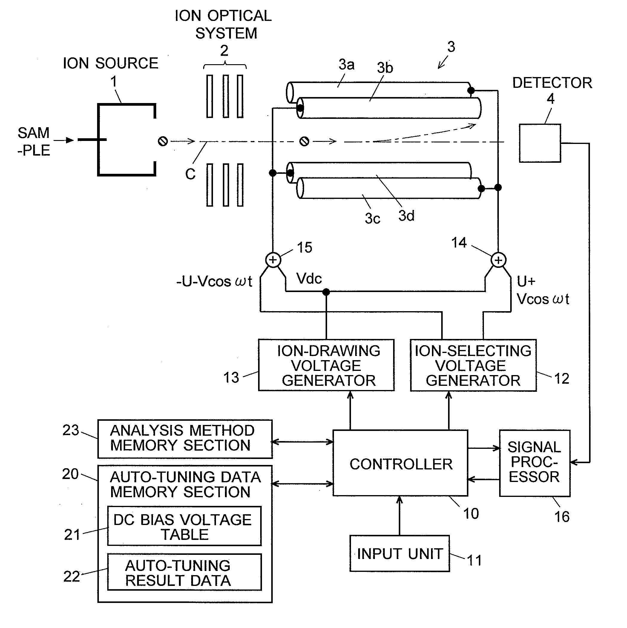
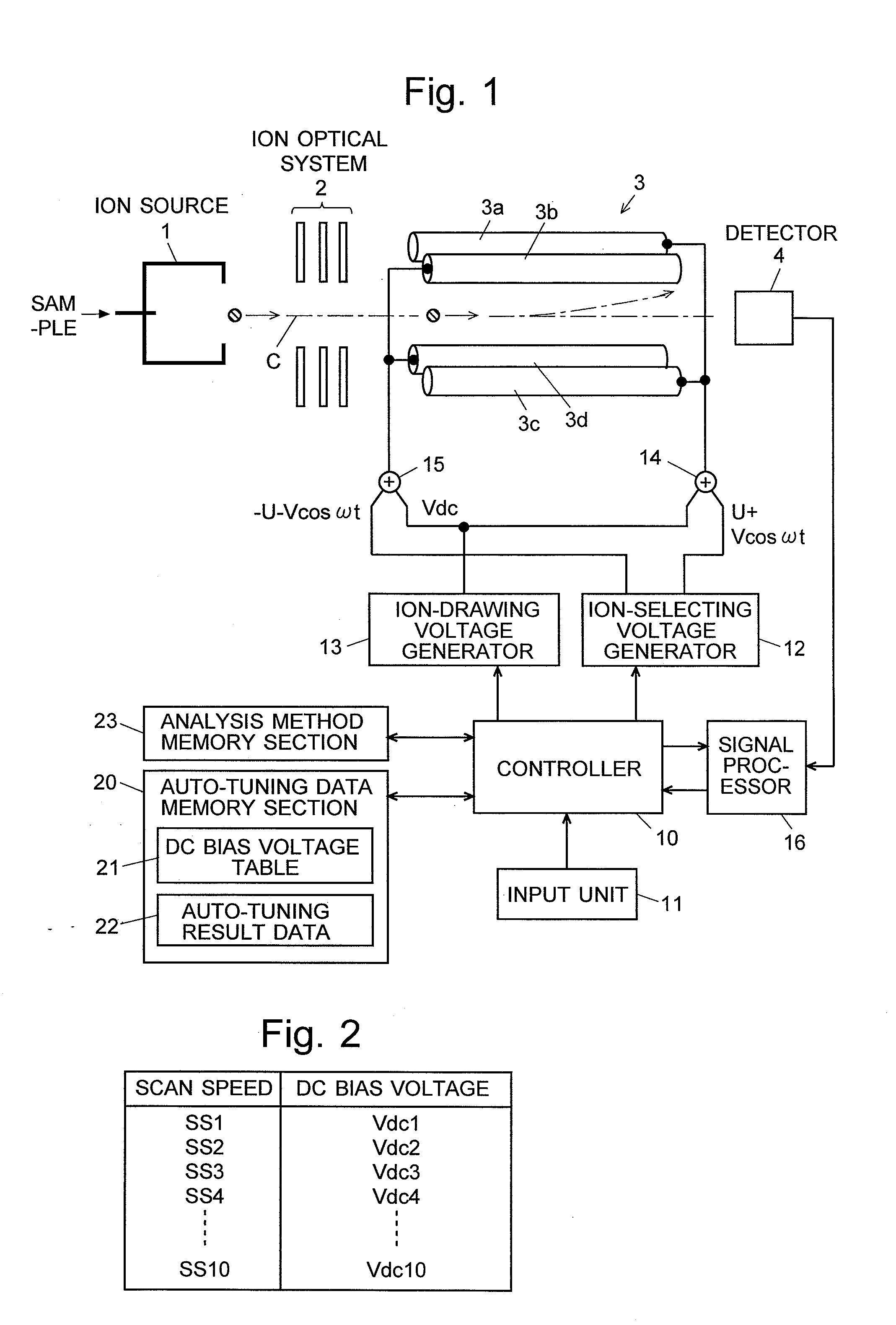
[0062]An embodiment of the quadrupole mass spectrometer according to the first aspect of the present invention is described with reference to the attached drawings (the first embodiment). FIG. 1 is a schematic diagram of the main section of the quadrupole mass spectrometer of the first embodiment.

[0063]As explained earlier, the apparatus has an ion source 1, an ion optical system 2, a quadrupole mass filter 3 and a detector 4. These are all enclosed in a vacuum chamber (which is not shown). In the quadrupole mass filter 3, four rod electrodes 3a, 3b, 3c and 3d are arranged so that they externally touch the inside of an imaginary cylindrical wall of a predetermined radius with its central axis lying on the ion beam axis C. Two rod electrodes opposing each other across the ion beam axis C are connected to each other, so that two rod electrodes neighboring each other in the circumferential direction are supplied with different voltages. To apply voltages to the rod electrodes 3a throug...

second embodiment

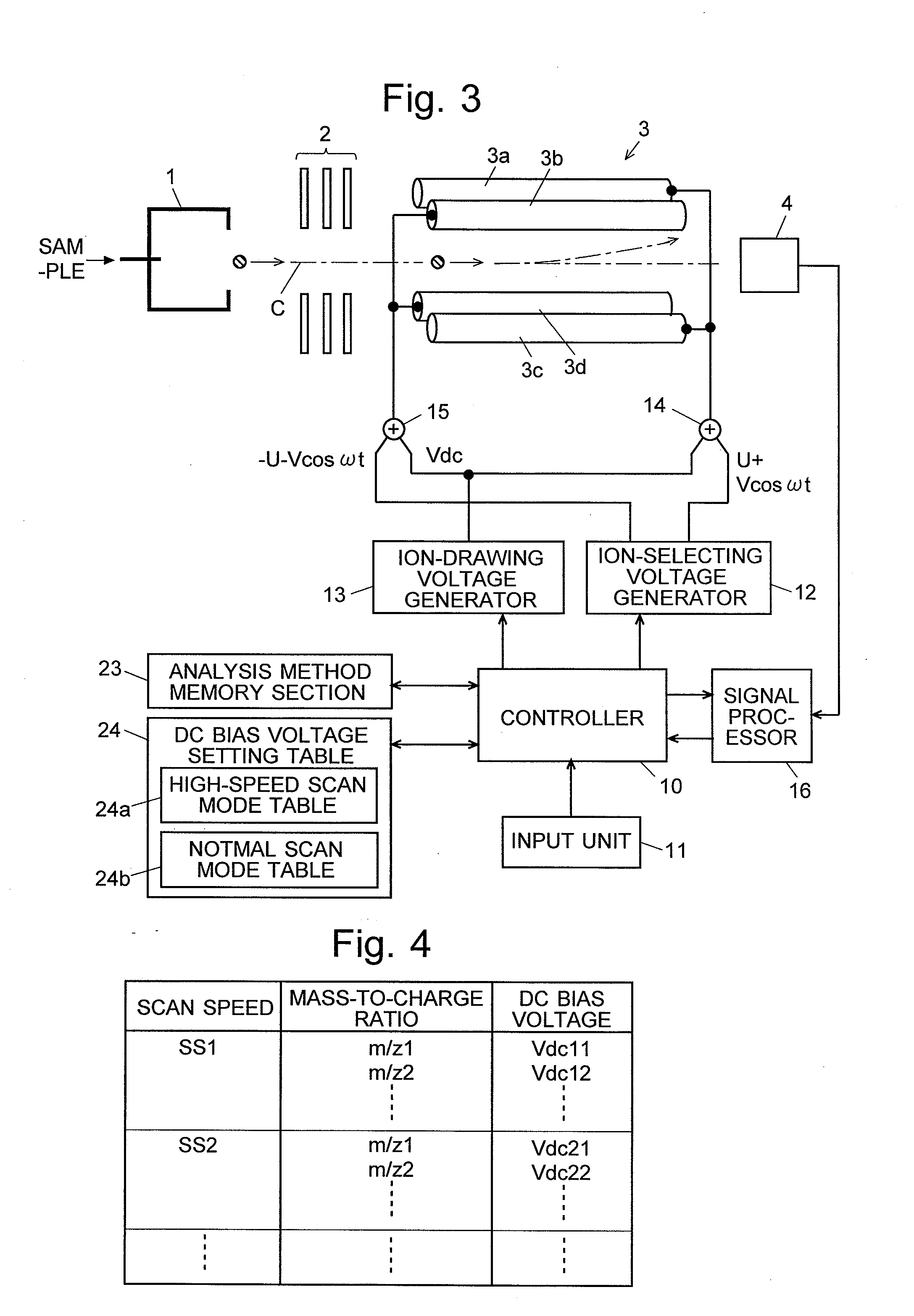
[0079]An embodiment of the quadrupole mass spectrometer according to the second aspect of the present invention is described with reference to the attached drawings (the second embodiment). FIG. 3 is a schematic diagram of the main section of the quadrupole mass spectrometer of the second embodiment. The following description omits detailed explanation of such components that are identical or equivalent to those of the quadrupole mass spectrometer of the first embodiment shown in FIG. 1.

[0080]In a scan measurement over a predetermined mass range, the controller 10 controls the ion-drawing voltage generator 13 according to the parameters read from the DC bias voltage setting table 24. The ion-drawing voltage generator 13 in turn applies a predetermined DC bias voltage Vdc to the voltage adders 14 and 15, respectively. To improve the detection sensitivity or mass resolution, the quadrupole mass spectrometer of the second embodiment controls the DC bias voltage Vdc so that it changes n...


PUM


Abstract

A table (21) for relating an appropriate DC bias voltage to each of a plurality of selectable scan speeds is stored beforehand in an auto-tuning data memory section (20). In an auto-tuning operation, a controller (10) determines the DC bias voltage corresponding to each scan speed by referring to the table (21) and fixes the output of an ion-drawing voltage generator (13) at that voltage. Subsequently, while changing the voltages applied to relevant sections such as an ion optical system (2), the controller (10) finds voltage conditions under which the detection signal is maximized. The conditions thus found are stored in an auto-tuning result data (22). In an analysis of a target sample, a DC bias voltage corresponding to a scan speed specified by an operator is obtained from the DC bias voltage table (21), and the optimal conditions for this voltage are obtained from the auto-tuning result data (22). Based on these items of information, conditions for the scan measurement are determined. This method prevents the deterioration in detection sensitivity, which will otherwise take place if the scan measurement is performed at a high scan speed.

Description

TECHNICAL FIELD[0001]The present invention relates to a quadrupole mass spectrometer using a quadrupole mass filter as a mass analyzer for separating ions according to their mass-to-charge ratios (m / z).BACKGROUND ART[0002]The quadrupole mass spectrometer is a well-known type of mass spectrometer using a quadrupole mass filter as a mass analyzer for separating ions according to their mass-to-charge ratios. FIG. 11(a) is a schematic diagram showing the configuration of a typical quadrupole mass spectrometer. In this quadrupole mass spectrometer, sample molecules are ionized by an ion source 1, such as an electron-impact ionizer. The ions thus produced are then converged (and accelerated in some cases) by an ion optical system 2, such as an ion lens, and introduced into a space extending along the major axis of a quadrupole mass filter 3 consisting of four rod electrodes. A voltage generated by superposing a direct-current (DC) voltage on a radio-frequency voltage is applied to each of...

Claims


Application Information

Patent Timeline
IPC IPC(8): H01J49/42
CPCH01J49/022H01J49/429H01J49/4215
Inventor MUKAIBATAKE, KAZUOMIZUTANI, SHIROKAWANA, SHUICHI
Owner SHIMADZU CORP
Why Eureka
Try Eureka