
Plasma reactor

a reactor and plasma technology, applied in the field of plasma reactors, can solve the problems of large amount of hydrogen that cannot be generated, the target gas treatment amount cannot be increased, and the efficiency of hydrogen generation cannot be raised, so as to achieve excellent activation ability and reaction efficiency, generate a large amount of hydrogen, and high electrode durability

Inactive Publication Date: 2010-08-05
NGK INSULATORS LTD
View PDF5 Cites 10 Cited by
  • Summary
  • Abstract
  • Description
  • Claims
  • Application Information

AI Technical Summary

Benefits of technology

[0009]The method described in the Patent Document 1 has the advantage that hydrocarbon can be reformed at relatively low costs under the mild conditions of low temperature (80 to 120° C.) and ordinary pressure in comparison with the conventional methods. However, the methods described in the Patent Document 1 has a problem of a narrow reaction region because a needle-shaped electrode and the like are used as the pair of electrodes, and thereby the hydrogen generation efficiency cannot be raised unless a reactor having a small internal diameter is used. Therefore, there arise problems that the target gas treatment amount cannot be increased and that a large amount of hydrogen cannot be generated. In addition, there arises a problem that durability of the electrodes is insufficient because the needle-shaped electrode and the like have large thermal deterioration upon discharge.
[0011]The present invention has been made in view of the aforementioned problems and provides a plasma reactor having excellent activation ability and reaction efficiency of the reforming reaction and being capable of generating a large amount of hydrogen with high durability of the electrodes besides the fact that the hydrogen generation efficiency hardly deteriorates even when the internal diameter of the reactor is increased.
[0024]A plasma reactor of the present invention is excellent in activation ability and reaction efficiency of the reforming reaction, can generate a large amount of hydrogen, and has high electrode durability besides the fact that the hydrogen generation efficiency hardly deteriorates even when the internal diameter of the reactor is increased.

Problems solved by technology

However, the methods described in the Patent Document 1 has a problem of a narrow reaction region because a needle-shaped electrode and the like are used as the pair of electrodes, and thereby the hydrogen generation efficiency cannot be raised unless a reactor having a small internal diameter is used.
Therefore, there arise problems that the target gas treatment amount cannot be increased and that a large amount of hydrogen cannot be generated.
In addition, there arises a problem that durability of the electrodes is insufficient because the needle-shaped electrode and the like have large thermal deterioration upon discharge.
However, since the apparatus described in the Patent Document 2 or 3 employs a pellet type catalyst as the catalyst, the contact among the catalysts is a point contact, which is inferior in heat transfer among the catalysts.
Therefore, there is a problem of low activation ability of the reforming reaction.
In addition, in the case of employing the packed bed method, since the target gas to be reformed passes through a gap among the pellet type catalysts filled in the reformer, it cannot be used only in a range of a space velocity of several thousands h−1 or less of the target gas to be treated.
Therefore, because the target gas treatment speed cannot be enhanced, there is a problem of impossible generation of a large amount of hydrogen.

Method used


Image

  • Plasma reactor
  • Plasma reactor

Examples


example 1

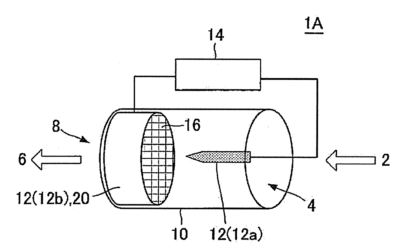
[0086]A plasma reactor 1A as shown in FIG. 1 was manufactured. As the reformer reactor 10, a cylindrical body composed of stainless steel and having an inner diameter of 30 mm, a thickness of 5 mm, and a length of 70 mm was used for the container portion. Inside the stainless steel cylindrical body was disposed alumina as an insulator, and the honeycomb electrode 12b and the linear electrode 12a were arranged on the insulator.

[0087]As the honeycomb electrode 12b, there was used a honeycomb structure 20 composed of silicon carbide (content of 75 mass %) and having a plurality of cells 16 functioning as gas flow passages and separated and formed by partition walls. As the honeycomb structure 20, there was cut out and used a silicon carbide diesel particulate filter (trade name: SiC-DPF, produced by NGK Insulators, Ltd.) for trapping particulate matter contained in an engine exhaust gas or the like.

[0088]More specifically, it had a circular columnar shape having a square cell shape, a ...

example 2

[0091]A plasma reactor was manufactured in the same manner as in Example 1 except that a catalyst was loaded on the partition walls of the honeycomb electrode. The catalyst was loaded by the following method.

[0092]After impregnating an alumina powder (specific surface area of 107 m2 / g) serving as carrier fine particles with a (rhodium nitrate (Rh(NO3)3) aqueous solution containing catalyst component rhodium in advance, it was dried at 120° C. and then fired at 550° C. for 3 hours in the atmosphere to obtain catalyst-coated fine particles. The mass ratio of rhodium to alumina was 0.5 mass %.

[0093]To the catalyst-coated fine particles were added a dispersion medium (water) and alumina sol, and its pH was adjusted to 4 by a nitric acid aqueous solution to obtain coating liquid (slurry). After the partition walls were coated by immersing the honeycomb electrode in the slurry, it was dried at 120° C. and then fired at 550° C. for 1 hour in a nitrogen atmosphere to load a catalyst on the ...

example 3

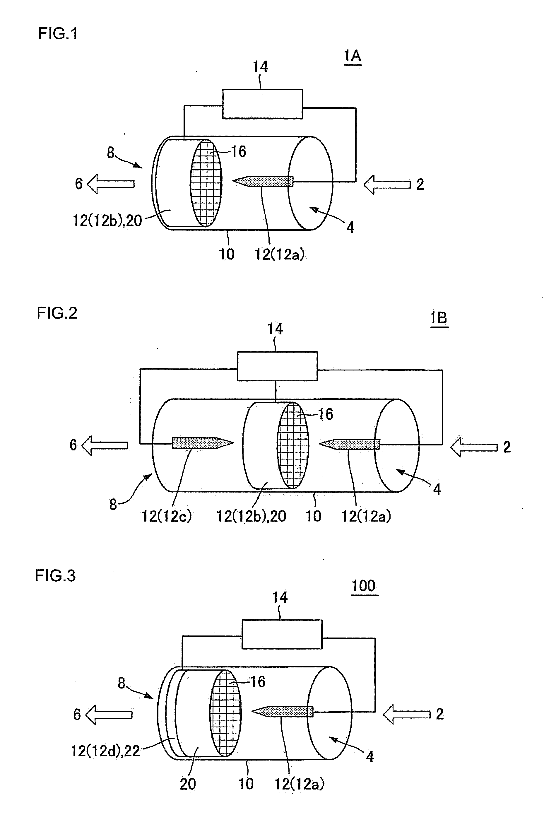
[0094]A plasma reactor 1B as shown in FIG. 2 was manufactured. The plasma reactor 1b was manufactured in the same manner as in Example 2 except that, as a pair of electrodes 12, a pair of linear electrodes 12a, 12c were disposed so as to face each other with the honeycomb electrode 12b being sandwiched therebetween and that a circular cylindrical body composed of stainless steel and having an inner diameter of 30 mm, a thickness of 5 mm, and a length of 120 mm was used for the container portion. The linear electrodes 12a, 12c were disposed to have a distance of 5 mm from the honeycomb electrode 12b. Incidentally, also in this plasma reactor 1B, the linear electrodes 12a, 12c served as positive electrodes.


PUM

PropertyMeasurementUnit
distanceaaaaaaaaaa
temperatureaaaaaaaaaa

Abstract

There is provided a plasma reactor provided with a reformer reactor having a feed port for target gas to be reformed and a discharge port for reformed gas, a pair of electrodes disposed to face each other in an internal space of the reformer reactor, and a pulse power source for applying a pulse voltage to the electrodes. One of the electrodes is a linear electrode, and the other electrode is a honeycomb electrode which is composed of a conductive ceramic and has a plurality of cells functioning as gas flow passages and separated and formed by partition walls.

Description

TECHNICAL FIELD[0001]The present invention relates to a plasma reactor generating plasma between a pair of electrodes and proceeding a reforming reaction by the plasma.BACKGROUND ART[0002]In recent years, hydrogen is in the spotlight as clean energy. As a process for obtaining hydrogen, a reforming reaction of hydrocarbon or the like has been known. However, generally, since high temperature of 700 to 900° C. is required for the hydrocarbon-reforming reaction, there are problems that the reforming apparatus is large and that great activation energy and long activation time are required for allowing the reaction to proceed. Therefore, there is investigated a technique where a pulse voltage or the like is applied to a pair of electrodes to generate plasma to perform a reforming reaction at low temperature with high efficiency by the use of the plasma.[0003]For example, there have been proposed a method for generating hydrogen, where a mixed gas of alcohol and water vapor is used as th...

Claims


Application Information

Patent Timeline
Patent Type & Authority Applications(United States)
IPC IPC(8): B01J19/08B01J35/00
CPCB01J19/088H05H2245/1215B01J2219/0811B01J2219/0826B01J2219/0832B01J2219/0835B01J2219/0875B01J2219/0892C01B3/342C01B2203/0233C01B2203/0244C01B2203/0261C01B2203/0861H05H1/24H05H2001/4697B01J2219/0809H05H1/48H05H1/471H05H1/475H05H2245/17
Inventor TAKAHASHI, MICHIOSAKUMA, TAKESHI
Owner NGK INSULATORS LTD
Learn More