Peeling member, member for forming peeling member, method of manufacturing peeling member, image remover, image forming and removing system, and image removing method

a peeling member and peeling technology, applied in the field of peeling members, can solve the problems of re-pulling wastepaper pulp quality, waste of paper or data, and generated waste of materials that require the use of landfills, and achieve the effects of removing the image formed on the recording material stably and completely, and large nip width

Inactive Publication Date: 2010-08-05
RICOH KK
View PDF18 Cites 5 Cited by
  • Summary
  • Abstract
  • Description
  • Claims
  • Application Information

AI Technical Summary

Benefits of technology

[0041]Further, with the organic polymer compound layer, it is possible to prevent a component of the thermoplastic composition layer formed on the surface of the organic polymer compound layer from being transferred to the rubber elasticity layer. Therefore, even if the same peeling member is used for a long term, there is little change in the physical properties of the rubber elasticity layer, such as the modulus of elasticity. Accordingly, it is possible to repeatedly remove the image formed on the recording material stably and completely.
[0042]Further, according to one embodiment of the present invention, the rubber elasticity layer employed may have a relatively large thickness. Therefore, it is possible to ensure a sufficiently large nip width even in the case of using a rigid body such as metal as the pressure member opposed to the peeling member.
[0043]Further, the heating part may be provided inside the pressure member so that the pressure member may be used as a heat and pressure member. This facilitates heat conduction to the recording material in the nip, thus making it possible to perform image removal at high speed. Further, since the rubber elasticity layer and the organic polymer compound layer are extremely lower in thermal conductivity than metal material, heat is less easily conductible to the base body side across the rubber elasticity layer, so that the temperature increases only at and near the surface of the peeling member inside the nip formed by the peeling member and the heat and pressure member. That is, since the temperature increases only where the heat capacity is low, the temperature of the peeling member and the thermoplastic image forming substance adhering to the peeling member is easily reducible in a process after passing through the nip.
[0044]Therefore, when the recording material is separated from the peeling member, the temperature of the thermoplastic image forming substance on the recording material and the thermoplastic composition layer of the peeling member has been rapidly reduced, so that it is possible to prevent cohesion failure from occurring in the thermoplastic image forming substance on the recording material and the thermoplastic composition layer of the peeling member to cause the thermoplastic image forming substance to remain on the recording material or transfer in reverse the thermoplastic composition layer of the peeling member to the recording material.
[0045]Further, if the peeling member is provided with a relatively thick rubber elasticity layer, and a roller member having high rigidity, such as a metal roller member, is employed as the pressure member opposed to the peeling member to form the nip, the recording material that has passed through the nip is disposed to be conveyed along the peripheral surface of the highly rigid roller member (pressure member). Because of this disposition, the recording material conveyed for image removal acts to be apart from the peeling member after passing through the nip, thus resulting in satisfactory separation of the recording material and the peeling member.
[0046]Further, according to a method of manufacturing a peeling member according to one embodiment of the present invention, the peeling member can be manufactured with ease at low cost.

Problems solved by technology

Therefore, in terms of the global environment, it has been an important social issue to protect forests by reducing paper consumption and preventing a decrease in forests due to logging.
Further, since paper includes incombustible or non-decomposable inorganic components, wasted materials that require the use of landfills are generated at a certain ratio when paper is discarded.
In these years, however, it has become difficult to newly reserve landfills, so that also in terms of waste reduction, it remains a social issue to reduce paper consumption.
There are many problems, however, in the process of collecting wastepaper and turning it into recycled paper, such as the possibility of leakage of corporate classified papers or data at the time of collecting wastepaper, time and effort for sorting wastepaper by paper type, and degradation of the pulp quality of re-pulped wastepaper.
However, these rubber materials are low in adhesion to toner, which is a thermoplastic image forming substance, so that the image on the recording material cannot be completely removed.
However, it is difficult to remove a low-density gradation image.
Further, there is a problem in that even when reusable recording material is formed by adding a composition that reduces adhesion to an image forming substance to the recording material to be used, and an attempt is made to remove an image formed on the reusable recording material by thermal transfer, which does not employ an image removal accelerating liquid, the image on the recording material can hardly be removed if the recording material is formed so as to present an image fixing characteristic sufficient for practical use, because the adhesion of the image forming substance to the rubber material becomes lower than the adhesion of the image forming substance to the recording material.
Further, if metal or a plastic film without a thermoplastic resin surface layer is employed as a peeling member, it is difficult to remove an image forming substance in concave parts at a paper surface.
In particular, it is difficult to completely remove image forming substance particles that form background fogging and adhere alone or a low-density image.
If there is a “high” image of a secondary color around a “low” image such as a monochromatic gradation image, it is difficult for the peeling member to come into contact with the “low” image.
Therefore, even when an image removal accelerating liquid is applied from the surface of the image, the image removal accelerating liquid is blocked by the image forming substance and is prevented from reaching the cellulose fibers of the paper, thus making it difficult to remove the image.
However, even if the amount of the liquid applied is only a little, repeated use of the recording material causes problems such as generation of wrinkles or curl and occurrence of a conveyance jam due to the generation of curl at the time of processing in an image forming apparatus or image remover.
Thus, the number of times the recording material can be repeatedly used cannot be increased.
Further, adding a large amount of the liquid causes problems such as the need for a large amount of energy to dry the absorbed liquid and a change in the size of the recycled recording material.
However, it is difficult to completely remove the image even with a peeling member (peeling belt) where a heat-melt resin is provided on an endless belt of metal or a heat-resistant organic polymer material such as a polyimide film.
In particular, in the case of forming a color image including a secondary color and a tertiary color on the recording material, multiple layers of the image forming substance are formed, and it is difficult to remove a “low” low-density image around a multi-layer “high” image or the image forming substance that has been scattered around the image at the time of the transfer of the image to the recording material.
Further, there are also problems in the case of using an endless belt (peeling belt) as a peeling member.
For example, if the peeling belt deviates to one side because of its continuous use, it is difficult to correct the deviation.
If the deviation is forcibly corrected, an uneven tension is exerted on the peeling belt in its widthwise directions, so as to cause deformation of the peeling belt and reduction of its useful service life.
This makes it extremely difficult to solve the problem of the deviation of the peeling belt.
A peeling member having such a configuration as described in Patent Document 3 or Patent Document 4 has the problem of low adhesion between the rubber layer and the thermoplastic layer.
Therefore, there is a problem in that if recording material having an adhesion (fixing) characteristic sufficient for practical use with respect to the image forming substance is used, the image forming substance on the recording material cannot be completely removed or the thermoplastic layer on the recording material is peeled off from the rubber layer so as to be transferred in reverse onto the recording material.
Further, there is a problem in the case of using recording material having low adhesion to the image forming substance.
However, since the molecules of the rubber-like composition can move relatively freely as a characteristic of the rubber-like composition, a component of the thermoplastic resin layer provided on the rubber elasticity layer or a component of the image forming substance transferred onto the thermoplastic resin layer is mixed into the rubber elasticity layer, so that continuous use causes the rubber elasticity layer to swell and deform or makes it impossible to remove the image forming substance from the recording material.

Method used


Image

  • Peeling member, member for forming peeling member, method of manufacturing peeling member, image remover, image forming and removing system, and image removing method
  • Peeling member, member for forming peeling member, method of manufacturing peeling member, image remover, image forming and removing system, and image removing method
  • Peeling member, member for forming peeling member, method of manufacturing peeling member, image remover, image forming and removing system, and image removing method

Examples


first embodiment

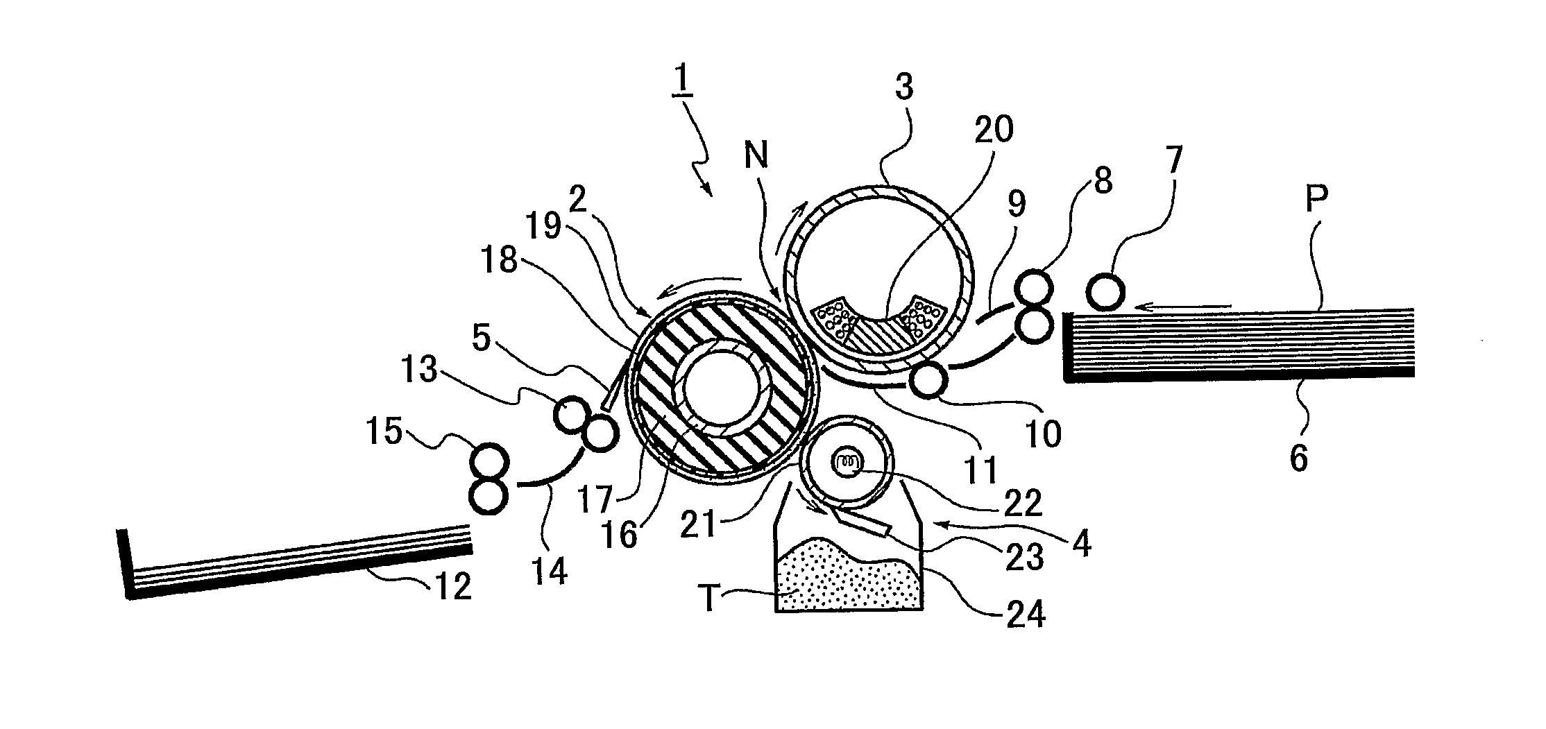
[0062]FIG. 1 is a diagram showing an image remover 1 including a peeling roller 2 as a peeling member according to a first embodiment of the present invention.

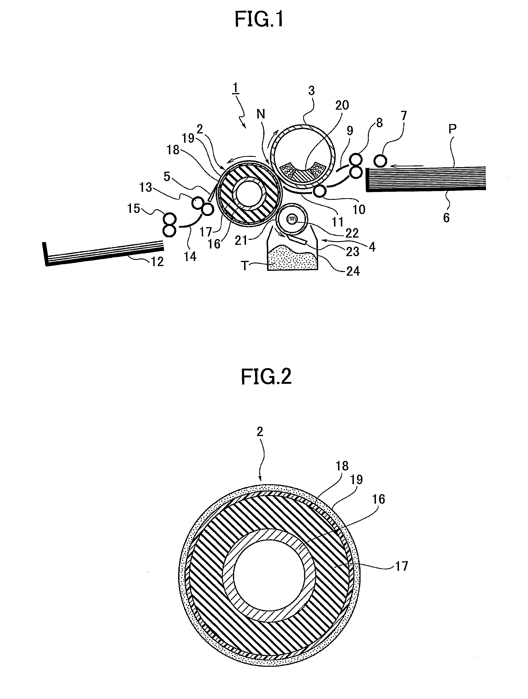
[0063]FIG. 2 is a cross-sectional view of the peeling roller 2.

[0064]According to this embodiment, the image remover 1 is a unit or apparatus that removes a thermoplastic image forming substance (hereinafter, “image forming substance”) forming an image from recording material (recording medium) having the image formed thereon, thereby removing or erasing the image from the recording material, in an image forming apparatus such as a copier, printer, or facsimile machine.

[0065]Referring to FIG. 1, the image remover 1 according to this embodiment includes the peeling roller 2 rotatably supported to serve as a peeling member; a heat and pressure roller 3 rotatably supported in contact with the peeling roller 2 so as to serve as a pressure member, the heat and pressure roller 3 including a magnet coil for IH (Induction Heating) (IH...

second embodiment

[0166]FIG. 10 is a schematic diagram showing a configuration of an image remover 1a having the peeling roller 2 used as a peeling member according to a second embodiment of the present invention. In the below-described image remover 1a according to the second embodiment of the present invention, like components are denoted by like reference numerals as of the image remover 1 according to the first embodiment of the present invention and are not further explained.

[0167]As shown in FIG. 10, the image remover 1a according to an embodiment of the present invention includes an inverted conveyance part 52. In a case where an image is formed on each side of the recording material P, the inverting conveyance part 52 is configured to invert the recording material P and convey the recording material P to a temporary storage tray 51 instead of conveying the recording material P to the paper discharge tray 12 after an image (image forming substance) on one side of the recording material P is re...

third embodiment

[0173]FIG. 11 is a schematic diagram showing a configuration of an image remover 1b having an endless peeling belt 62 used as a peeling member according to a third embodiment of the present invention. In the below-described image remover 1b according to the third embodiment of the present invention, like components are denoted by like reference numerals as of the image removers 1 and 1a according to the first and second embodiments of the present invention and are not further explained.

[0174]As shown in FIG. 11, the image remover 1b according to an embodiment of the present invention has the endless peeling belt 62 spanning around a driving roller 63, a separation roller 64, an opposing roller 65, and a driven roller 66. A tension roller 67 contacting the outer surface of the peeling belt 62 provides a predetermined tension to the peeling belt 62. In this embodiment of the present invention, the separation roller 64 and the opposing roller 65 function as driven rollers. The peeling ...


PUM

PropertyMeasurementUnit
Young's modulusaaaaaaaaaa
thicknessaaaaaaaaaa
thicknessaaaaaaaaaa

Abstract

A peeling member to be used in an image remover configured to peel off and remove an image by thermal transfer from a recording material on which the image is formed of a thermoplastic image forming substance is disclosed that includes a base body; a rubber elasticity layer provided on the base body, the rubber elasticity layer being formed of a material having rubber elasticity; an organic polymer compound layer provided on the rubber elasticity layer, the organic polymer compound layer presenting no plasticity at a heating temperature for peeling off and removing the image on the recording material by the thermal transfer and having a Young fs modulus of 400 MPa to 6000 MPa at normal temperature; and a thermoplastic composition layer formed on the surface of the organic polymer compound layer so as to serve as an outermost surface layer presenting adhesion to the thermoplastic image forming substance.

Description

TECHNICAL FIELD[0001]The present invention relates to, for example, a peeling member for peeling off and removing an image by thermal transfer, the image being formed of a thermoplastic image forming substance on recording material by an image forming apparatus such as a copier, printer, or a facsimile machine; a member for forming the peeling member; a method of manufacturing the peeling member; an image remover having the peeling member; an image forming and removing system; and a method of removing an image.BACKGROUND ART[0002]In these years, a large amount of paper as recording material on which images are to be formed has been consumed because electrophotographic image forming apparatuses such as copiers, printers, and facsimile machines have become widely used. Here, paper used as recording material is made from wood pulp as a raw material. Therefore, in terms of the global environment, it has been an important social issue to protect forests by reducing paper consumption and ...

Claims


Application Information

Patent Timeline
Patent Type & Authority Applications(United States)
IPC IPC(8): B41M5/40
CPCG03G15/2028G03G7/0086B41M7/0009G03G21/00
Inventor MURAKAMI, KAKUJISAITOH, MASATOSHI
Owner RICOH KK
Why Eureka
Try Eureka