

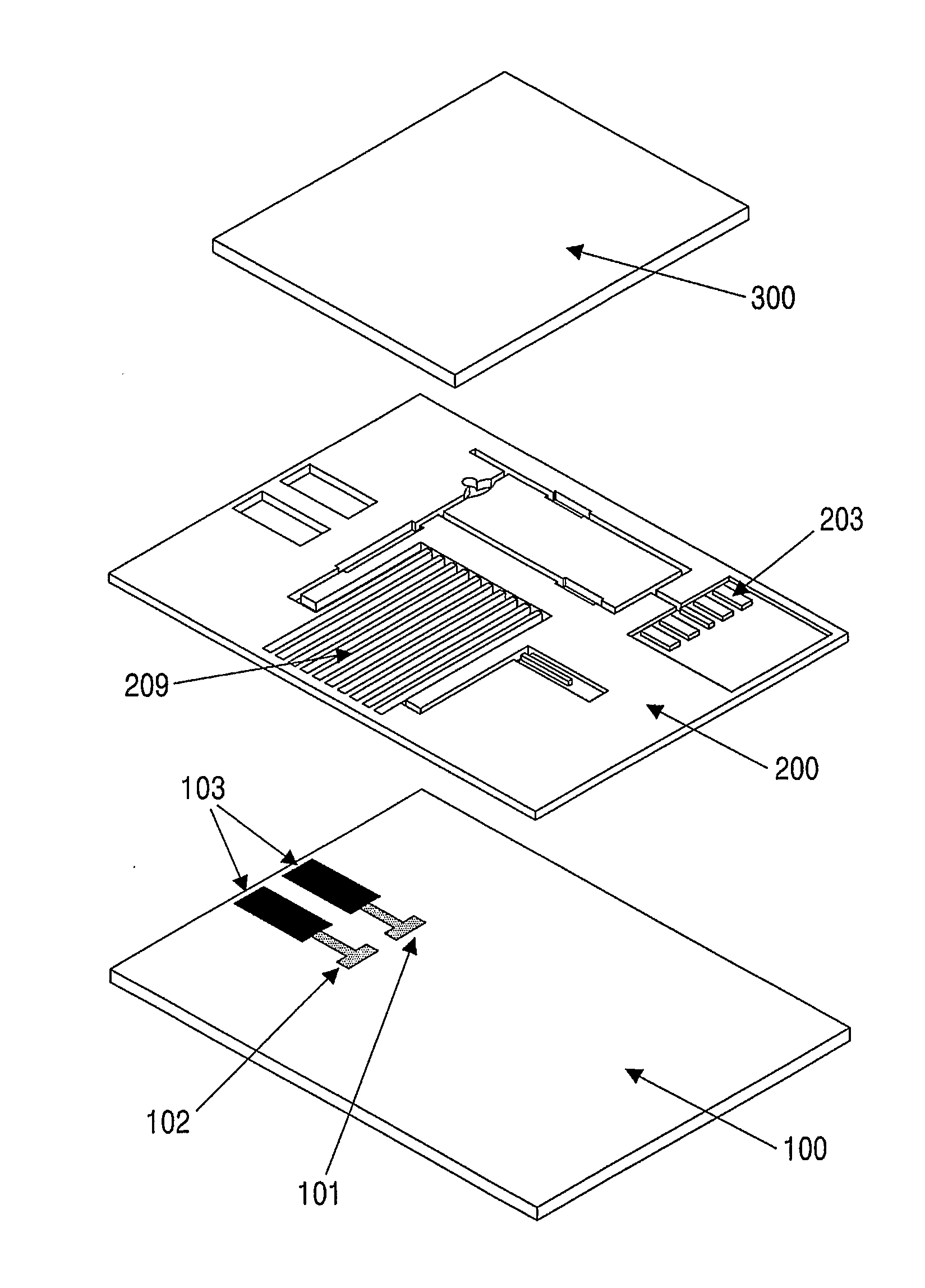
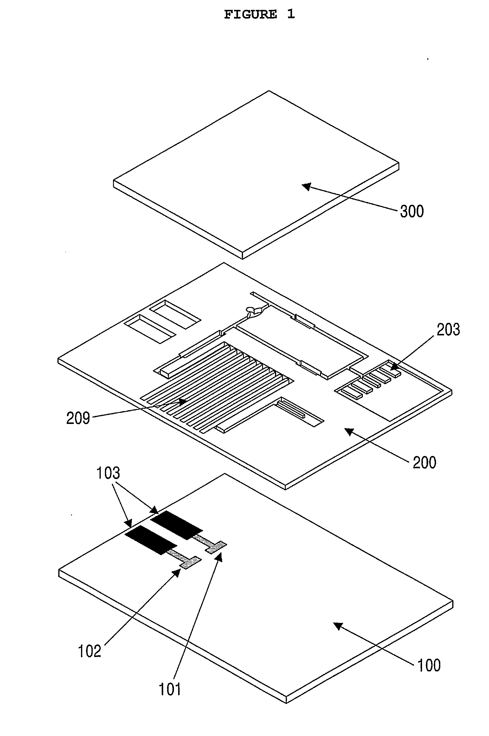
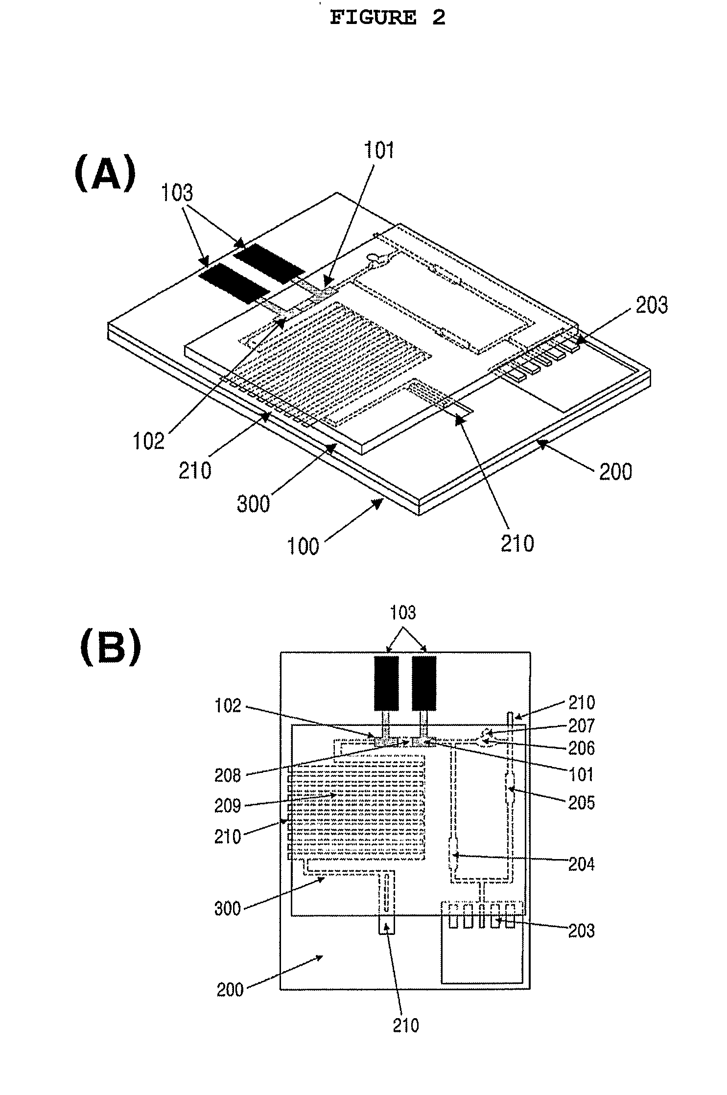
Microfluidic sensor complex structure
a microfluidic and sensor technology, applied in the field of microfluidic sensor complex structure, can solve the problems of difficult mass production of conventional biosensors in lab-on-chips, complicated structure of conventional biosensors, and difficult production of conventional structures at low cost and high reliability, and achieves convenient handling and shows sensitivity and selectivity
- Summary
- Abstract
- Description
- Claims
- Application Information
AI Technical Summary
Benefits of technology
Problems solved by technology
Method used
Image

Examples
example 1
Fabrication of Microfluidic Sensor for Quantitative Analysis of Myoglobin 1
[0087](1) Preparation of Electrode and Microfluidic Channel Passage
[0088]A microfluidic channel passage was formed using photolithography, which is generally used in semiconductor technology. In this regard, an acryl-coated polyethylene terephthalate (PET) film was used as a plate. A carbon paste was screen-printed on the film to form a working electrode, an electrode connection and a fluidity sensing electrode. A reference electrode and an electrode connection were formed with a silver paste. A dry photoresist film was thermally pressurized against the film on which the electrodes were formed, followed by the formation of a microfluidic channel passage using an exposure system. The microfluidic channel passage was designed with a CAD program and printed on an OHP film, which was then used as a pattern mask. After being exposed to a UV beam at a predetermined dose, the dry photoresist film was etched with a 2...
example 2
Fabrication of Microfluidic Sensor for Quantitative Analysis of Myoglobin 2
[0092]A microfluidic sensor was fabricated in the same manner as set forth in Example 1, with the exception that a blood filter pad was provided at the sample inlet channel and a fluidity sensing electrode was installed at an end region of the absorbing channel.
[0093]The blood filter pad was commercially available from Lydall Filtration, identified as LyPore Grade 9389. Like the working electrode, the fluidity sensing electrode was prepared from a carbon paste.
example 3
Fabrication of Microfluidic Sensor for Quantitative Analysis of Myoglobin 3
[0094]A microfluidic sensor was fabricated in the same manner as explained in Example 1, with the exception that two verifying electrodes were further installed. The two verifying electrodes were formed of carbon paste and coated with BSA for a first verifying electrode and with IgG for a second verifying electrode.
[0095]Coated with BAS, the first verifying electrode was adapted to detect background signals while the second verifying electrode, coated with the same IgG as in the control line of a rapid kit, was adapted to monitor the solution of the enzyme conjugate by binding to unreacted enzyme conjugate, that is, to monitor saturation signals.
PUM
| Property | Measurement | Unit |
|---|---|---|
| temperature | aaaaa | aaaaa |
| pH | aaaaa | aaaaa |
| pH | aaaaa | aaaaa |
Abstract
Description
Claims
Application Information