

Liquid Lens System
a liquid lens and liquid technology, applied in the field of optical systems, can solve the problems of only being suitable for miniaturisation, affecting the gravity force and vibration of the liquid lens, and sealing between the first control element and the side wall of the chamber
- Summary
- Abstract
- Description
- Claims
- Application Information
AI Technical Summary
Benefits of technology
Problems solved by technology
Method used
Image

Examples
first embodiment
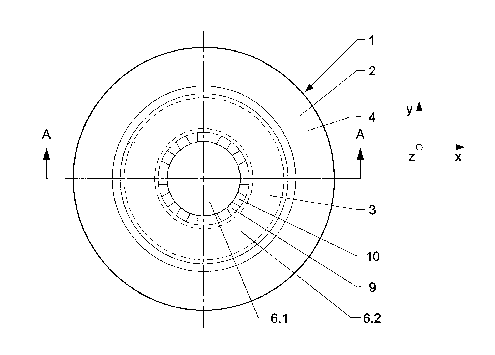
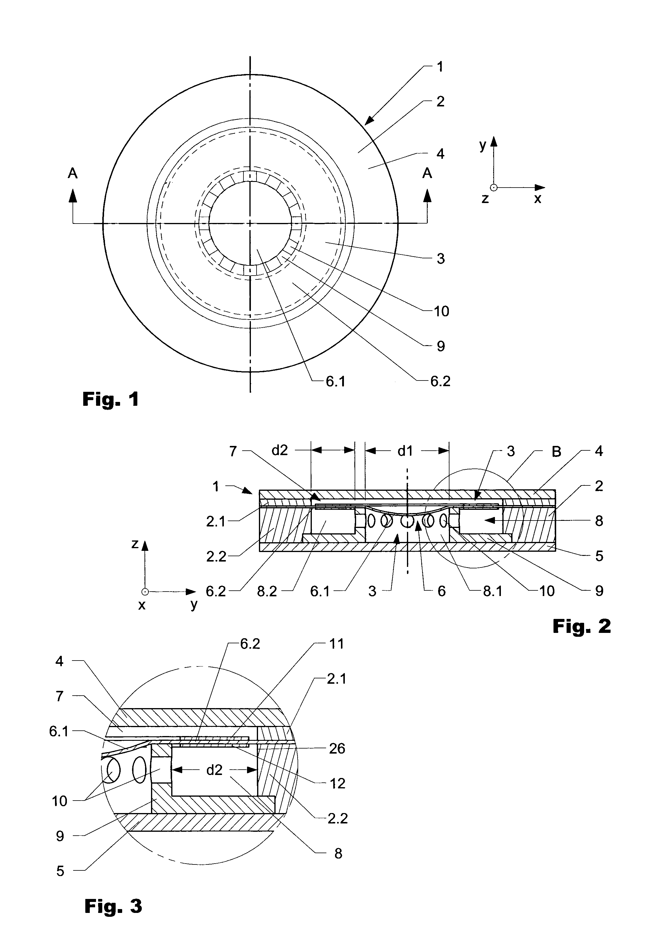
[0073]FIG. 1 shows a lens system 1 according to the invention in a top view, FIG. 2 shows a cross-cut through the lens system along line AA and FIG. 3 shows detail B according to FIG. 2.
[0074]The lens system 1 comprises an outer housing 2 with a central opening 3 which extends in axial direction (z-axis) through the housing 2. The central opening 3 is closed on either side of the housing 2 by an upper and a lower rigid panel 4, 5. A membrane 6 separates the opening 3 in a first upper and a second lower chamber 7, 8 which are filled by a fluid (liquid or gas, not shown in detail). In the shown embodiment the membrane 6 is fixed at its outer end in a prestretched manner to the housing 2 by clamping the membrane between an upper and a lower part 2.1, 2.2 of the housing 2. Inside the central opening 3 an annular holding frame 9 is visible which separates the membrane 6 into a first circular inner (with a diameter d1) and a second annular outer area 6.1, 6.2. In the shown embodiment the ...
third embodiment
[0080]FIG. 7 schematically shows a lens system 40 according to the invention in an undeformed manner (FIG. 7a) and in two deformed stages (FIGS. 7b and 7c). The lens system 40 comprises an outer housing 41 which encompasses a volume V which at least during operation is normally constant. Inside the housing 41 a first and a second membrane 42, 43 made out of an elastic material are arranged separating the inner volume of the housing 41 in three chambers 44, 45, 46. The chambers 44, 45, 46 are filled with different fluids having different optical characteristics. Each membrane 42, 43 is attached in a stretched manner to a holding ring (annular holding frame) 47, 48 which in the present embodiment is arranged at a certain distance to the rim of the membrane at an outer rim. In the present embodiment the holding rings 47, 48 have in general the same diameter. To achieve special effects, this diameter can be different. The membranes 42, 43 are at their outer rim attached to the housing 4...
fifth embodiment
[0085]FIG. 9a and FIG. 9b are showing an optical system 55 according to the invention. FIG. 9a shows the optical system 55 in an undeformed and FIG. 9b in a deformed manner. The optical system 55 comprises an outer housing 56 with a central opening 57 extending in axial direction z. At one end, the central opening 57 is closed by a rigid wall 58. A flexible membrane 59 extends across the opening 57 and is fixed at its outer end to outer housing 56. A chamber 60 having a volume V and which is filled by a fluid (liquid or gas) is delimited by the wall 58 and the membrane 59. An annular frame 61 is interconnected to the membrane 59 a certain distance d2 apart from the outer rim of the membrane 59. In that the annular frame 61 is pressed (here −z-direction) along a distal end directly or indirectly onto the surface of the membrane 59 the fluid inside the chamber 60 is rearranged and the membrane is deformed calotte-like as schematically shown in FIG. 9b in a convex manner. In that the c...
PUM
 Abstract
Description
Claims
Application Information