Fuel cell system and method of operating the fuel cell system

a fuel cell and system technology, applied in the direction of fuel cells, solid electrolyte fuel cells, electrical apparatus, etc., can solve the problems of difficult to carry out thermal self-sustained operation, low energy efficiency, and difficult to maintain the operating temperature of the sofc in thermally self-sustained operation, so as to improve the efficiency and efficiency of waste heat utilization, and improve the collection ratio of waste heat.

Inactive Publication Date: 2010-08-12
HONDA MOTOR CO LTD
View PDF6 Cites 33 Cited by
  • Summary
  • Abstract
  • Description
  • Claims
  • Application Information

AI Technical Summary

Benefits of technology

[0014]According to the present invention, the reformer is heated directly by the first heating mechanism, and heated indirectly by the second heating mechanism. Therefore, in the fuel cell system, even during the partial load operation where the generated heat energy is small, the operation condition values of the reformer required for thermally self-sustained operation (temperature condition value of the reformer) are maintained. Thus, the range where it is possible to carry out the thermally self-sustained operation using the partial load is expanded, and the thermal efficiency is improved.
[0015]Further, after the exhaust gas is supplied to the reformer and the first heat exchanger, and used as the heat medium and the heat source, the exhaust gas is supplied to the second heat exchanger again, as the heat medium for heating the cooling medium. Thus, the waste heat of the exhaust gas is utilized efficiently, and the collection ratio of the waste...

Problems solved by technology

Under the circumstances, it is difficult to maintain the operating temperature of the SOFC in the thermally self-sustained operation, i.e., using only the amount of heat energy generated from the SOFC without supplying additional heat from the outside.
However, in the technique disclosed in Japanese Laid-Open Patent Publication No. 2004-071312, since the excessive heat during the full load operation is accumulated in the heat accumulating material layer 5, and the accumulated heat is utilized during the partial load operation, the full load operation needs to be performed before the partial load operation.
Therefore, in the case of carrying out the partial load ope...

Method used


Image

  • Fuel cell system and method of operating the fuel cell system
  • Fuel cell system and method of operating the fuel cell system
  • Fuel cell system and method of operating the fuel cell system

Examples


first embodiment

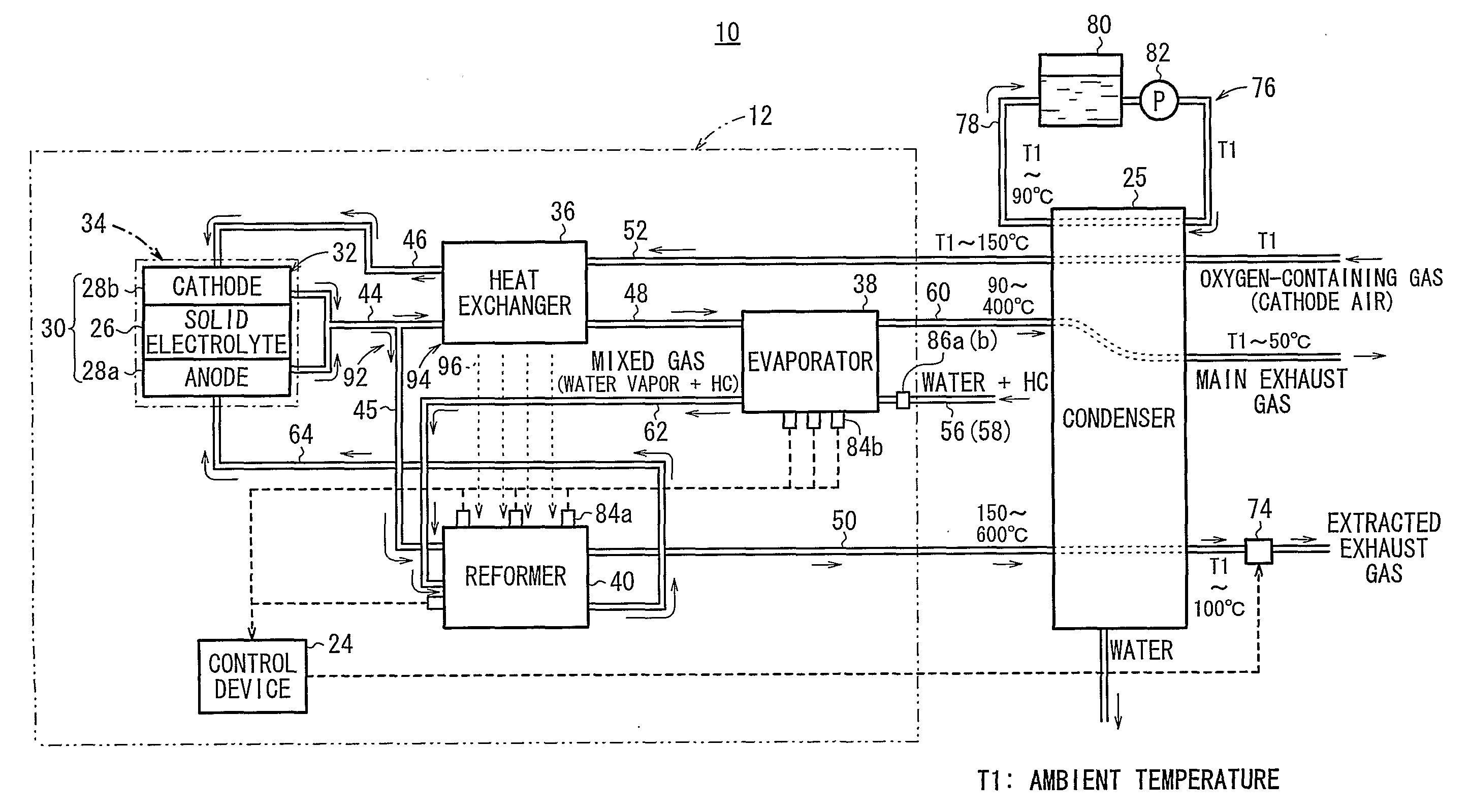
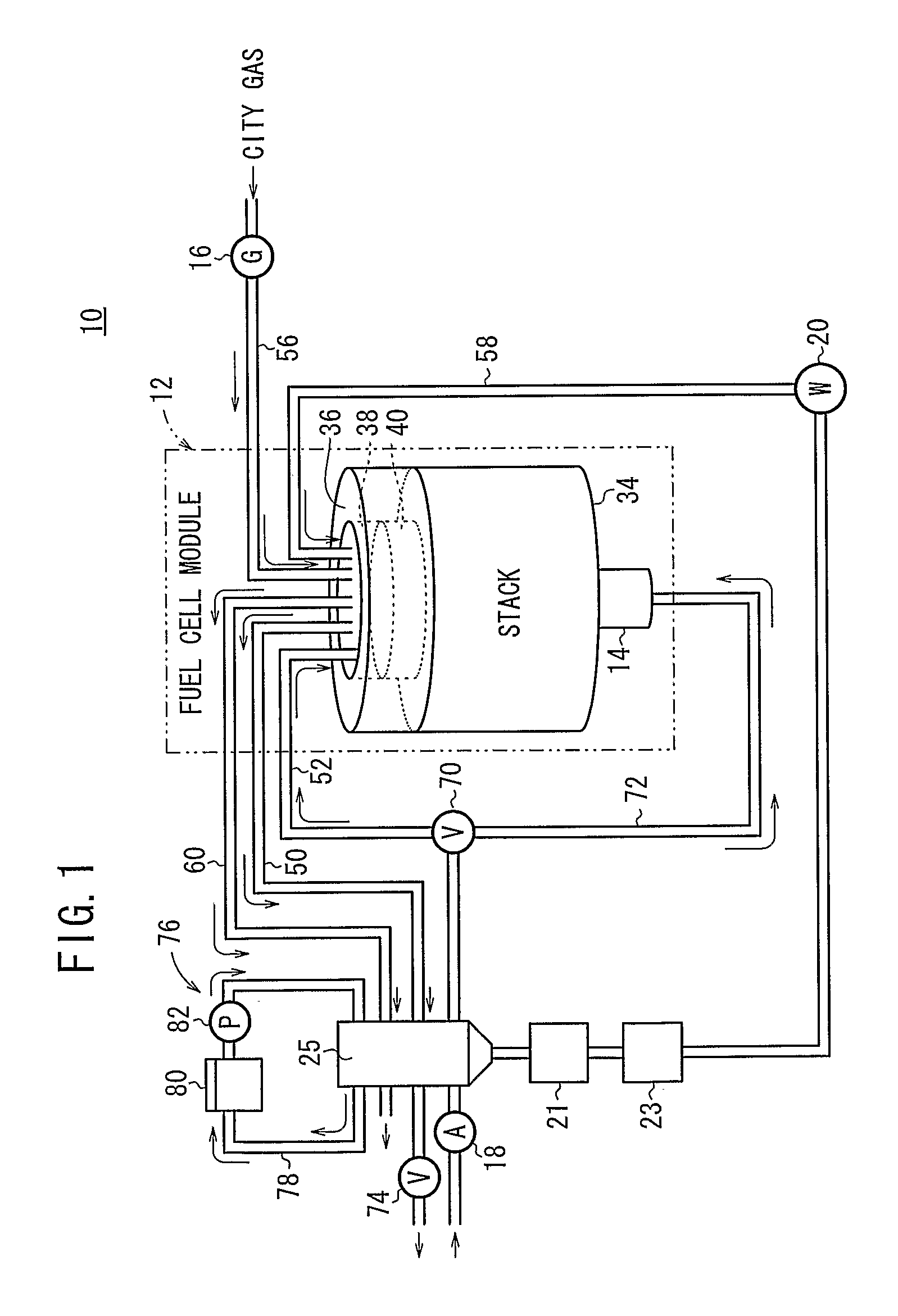
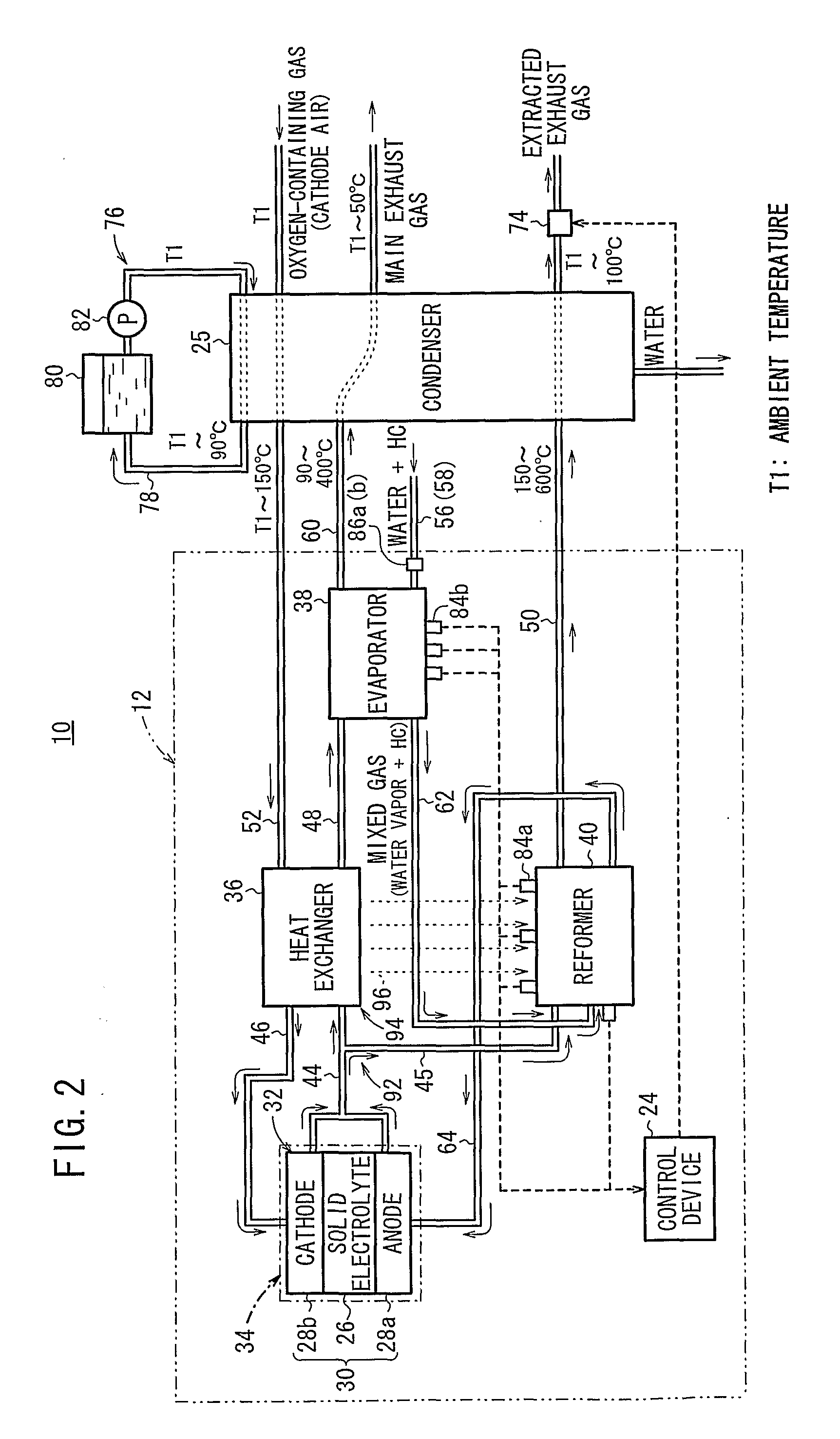
[0027]FIG. 1 is a diagram schematically showing structure of a mechanical circuit of a fuel cell system 10 according to the present invention. FIG. 2 is a diagram showing a gas extraction circuit of the fuel cell system 10. FIG. 3 is a circuit diagram showing the fuel cell system 10.

[0028]The fuel cell system 10 is used in various applications, including stationary and mobile applications. For example, the fuel cell system 10 is mounted on a vehicle. The fuel cell system 10 includes a fuel cell module 12 for generating electrical energy in power generation by electrochemical reactions of a fuel gas (hydrogen gas) and an oxygen-containing gas (air), a combustor (e.g., torch heater) 14 for raising the temperature of the fuel cell module 12, a fuel gas supply apparatus (including a fuel gas pump) 16 for supplying a raw fuel (e.g., city gas) to the fuel cell module 12, an oxygen-containing gas supply apparatus (including an air pump) 18 for supplying an oxygen-containing gas to the fuel...

third embodiment

[0071]FIG. 7 is a diagram schematically showing a gas extraction circuit of a fuel cell system 120 according to the present invention.

[0072]In the fuel cell system 120, instead of the second exhaust gas channel 48, a second exhaust gas channel 122 is connected to the heat exchanger 36. The second exhaust gas channel 122 is connected to the main exhaust pipe 60. In the reformer 40, an exhaust gas channel 124 is provided at a position corresponding to the outlet side of the branch exhaust gas channel 45. The exhaust gas channel 124 is connected to the evaporator 38, and functions as a channel for supplying the exhaust gas to the evaporator 38 as a heat source for evaporating water.

[0073]In the third embodiment, the evaporator 38 supplies the mixed fuel to the reformer 40, and the exhaust gas discharged from the reformer 40 is supplied to the evaporator 38 as the heat medium for evaporating the water. Therefore, the operation condition values (temperature condition values) of the evapo...


PUM


Abstract

A fuel cell system includes a first heating mechanism for supplying part of an exhaust gas discharged from a fuel cell stack after consumption in power generation reaction to a reformer, a second heating mechanism for supplying the remaining exhaust gas to a heat exchanger and supplying heat generated in the heat exchanger to the reformer, a condenser where the exhaust gas discharged from the reformer and the heater exchanger is supplied, a flow rate regulator valve provided downstream of the condenser for regulating the flow rate of the exhaust gas supplied in the reformer, and a control device for controlling the flow rate regulator valve such that operation condition values during a thermally self-sustained operation of the fuel cell system are maintained. A method of operating such a fuel cell system is also provided.

Description

TECHNICAL FIELD[0001]The present invention relates to a fuel cell system including a fuel cell stack, a first heat exchanger, and a reformer. The fuel cell stack is formed by stacking a plurality of fuel cells, and each of the fuel cells is formed by stacking an electrolyte electrode assembly and a separator. The electrolyte electrode assembly includes an anode and a cathode, and an electrolyte interposed between the anode and the cathode. The first heat exchanger heats an oxygen-containing gas before the oxygen-containing gas is supplied to the fuel cell stack. The reformer reforms a mixed fluid of raw fuel chiefly containing hydrocarbon and water vapor to produce a fuel gas. Further, the present invention relates to a method of operating the fuel cell system.BACKGROUND ART[0002]Typically, a solid oxide fuel cell (SOFC) employs an electrolyte of ion-conductive solid oxide such as stabilized zirconia. The electrolyte is interposed between an anode and a cathode to form an electrolyt...

Claims


Application Information

Patent Timeline
IPC IPC(8): H01M8/06
CPCH01M8/04014H01M8/04067H01M8/04373H01M8/04425H01M8/04776Y02E60/525H01M8/0662H01M8/12H01M8/2425Y02E60/521H01M8/0612Y02E60/50H01M8/2432
Inventor MIYAZAKI, TOMIO
Owner HONDA MOTOR CO LTD
Why Eureka
Try Eureka