Solar energy collecting system and method

a solar energy and collector technology, applied in solar heat systems, solar thermal energy generation, light and heating equipment, etc., can solve the problems of polymeric tubes, copper tubing is relatively heavy, and the thermal collector technology outlined above has a number of limitations, so as to reduce shipping costs, reduce costs, and reduce weight

Inactive Publication Date: 2010-08-19
MILL MASTERS
View PDF51 Cites 31 Cited by
  • Summary
  • Abstract
  • Description
  • Claims
  • Application Information

AI Technical Summary

Benefits of technology

[0008]In view of the above, it can be appreciated that the present invention provides various benefits over conventional solar energy collectors. The metal multiport tubes can be formed by extrusion, for example, extruding an aluminum alloy, and consequently can be produced at lower cost than extruded polymeric materials, copper tubing and copper sheet materials commonly used in solar energy collectors. Notably, the flat surfaces of the multiport tubes enable the tubes to be directly used as solar collectors without the addition of absorber plates or fins. Extruded aluminum multiport tubes are widely used in the automotive industry in condensers and charge air coolers, and therefore should be more readily available than extruded polymeric and copper tubing and from a greater number of sources. Extruded aluminum multiport tubes also have the advantage of being capable of assembly with manifolds using commercially available brazing materials, equipment, and methods. For example, braze rings can be used and brazing performed with a braze torch. The brazing process can be automated, similar to high volume automotive heat exchanger production methods. For a given level of heating capacity, the solar energy collection system of this invention can also be manufactured to have a relative low weight, minimizing shipping costs and allowing the system to be carried to rooftops and other elevated locations where solar collectors are commonly installed.

Problems solved by technology

The thermal collector technologies outlined above have a number of limitations.
Copper tubing is relatively heavy.
Polymeric tubes, while not susceptible to corrosion, are prone to distortion and UV degradation and are not capable of withstanding high temperatures.
Vacuum tubes are fragile, expensive, and require large amounts of space, and the glass tubes limit the size of the absorber fin or sheet.
Finally, the vacuum insulation method employed by vacuum tubes results in an array of tubes occupying a large space, with each glass vacuum tube containing a single copper round tube and a typical glass tube diameter of about 40 mm.

Method used


Image

  • Solar energy collecting system and method
  • Solar energy collecting system and method
  • Solar energy collecting system and method

Examples


Embodiment Construction

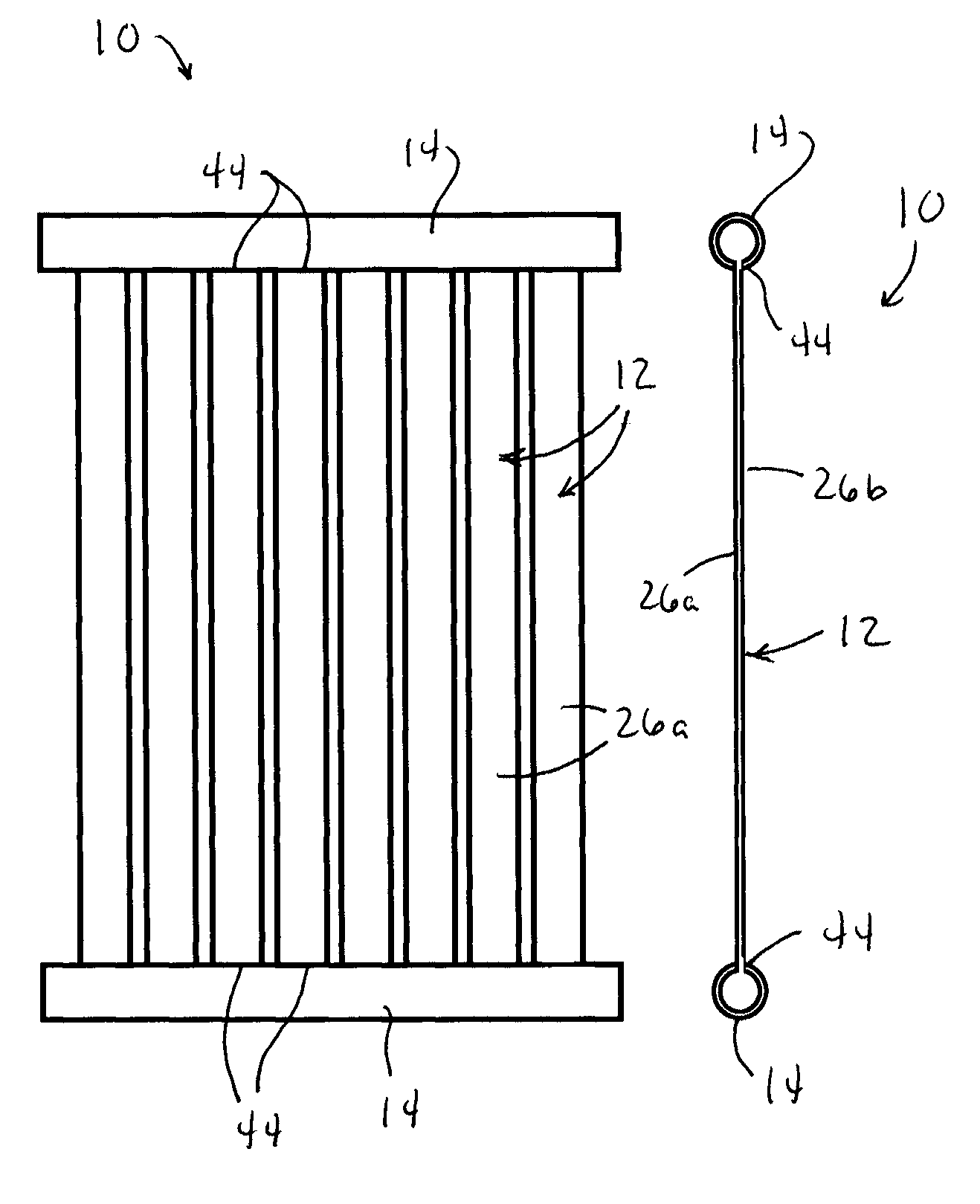
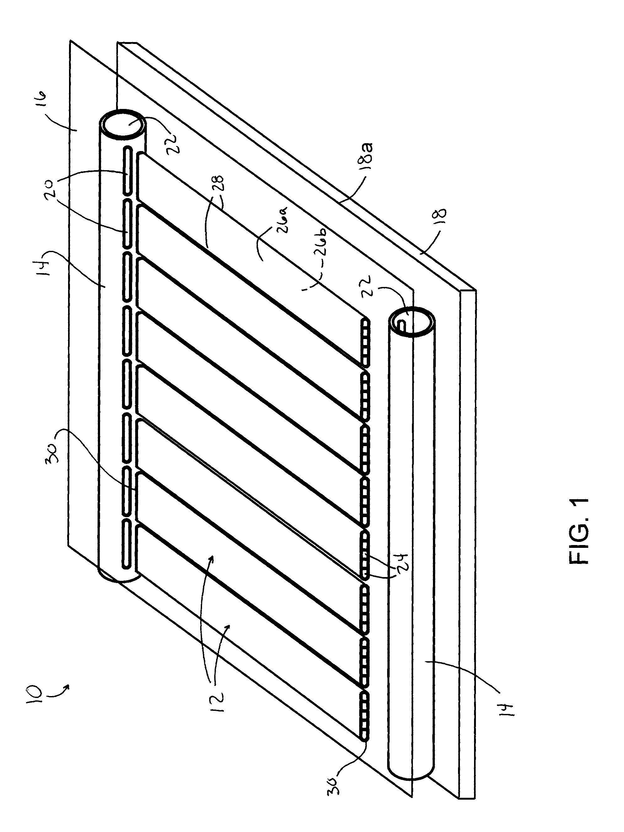
[0023]FIG. 1 schematically represents a solar energy collection apparatus, referred to below as a solar panel 10, according to an embodiment of the invention. The panel 10, which may be described as a solar collector or thermal collector, comprises multiple tubes 12 fluidically connected to a pair of manifolds 14, which form a fluid circuit between a pair of panels 16 and 18. The upper panel 16 (as oriented in FIG. 1) is above the tubes 12 and is preferably glazing or another material suitably transparent to solar radiation, whereas the lower panel 18 is beneath the tubes 12 and may be formed of various materials, including materials that have thermal insulating properties and / or reflective properties. For example, the lower panel 18 may have a reflective surface 18a as discussed below. The tubes 12 are represented as being aligned with slots 20 in the manifolds 14, into which the tubes 12 are inserted to create the fluid circuit that comprises the interior chambers 22 of the manifo...


PUM


Abstract

A solar energy collecting system and method suitable for hot water generation using solar energy. The system includes multiport tubes between inlet and outlet manifolds. The tubes are formed of a metallic material, each tube has oppositely-disposed first and second flat surfaces between lateral edges thereof, longitudinally-opposed first and second ends, and multiple fluid channels between the first and second ends that are in fluidic parallel to each other. The inlet and outlet manifolds are coupled to the first and second ends of the tubes so that chambers within the inlet and outlet manifolds are fluidically connected to the fluid channels of the multiport tubes. During operation of the system, a fluid flowing through the fluid channels of the tubes is heated by direct solar radiation impinging the first flat surfaces of the tubes and optionally by reflected solar radiation impinging the second flat surfaces of the tubes.

Description

CROSS REFERENCE TO RELATED APPLICATIONS[0001]This application claims the benefit of U.S. Provisional Application No. 61 / 153,748, filed Feb. 19, 2009, the contents of which are incorporated herein by reference.BACKGROUND OF THE INVENTION[0002]The present invention generally relates to solar energy collecting systems and methods for their use and production. More particularly, this invention relates to solar panels whose construction includes lightweight flat multi-channel tubes, and to solar energy collecting systems that mainly comprise the solar panels and a water tank. The solar panel is capable of achieving improved efficiency so that less collector area will be required to be installed or, for a given collector area, more hot water will be produced.[0003]Existing solar energy thermal collectors are generally available in three forms: formed plastic collectors, flat plate collectors, and evacuated tube collectors. Plastic collectors generally employ polymeric multi-channel tubes ...

Claims


Application Information

Patent Timeline
Patent Type & Authority Applications(United States)
IPC IPC(8): F24J2/24F24S10/70F24S50/20
CPCF24J2/245F24J2/265F24J2/4647F24J2/465Y02E10/47F24J2002/1061F24J2002/241F28F9/18Y02E10/44F24J2/5403F24S30/42F24S80/30F24S80/70F24S10/753F24S2023/84F24S10/742F24S2010/71
Inventor SHABTAY, YORAM LEONPANTHOFER, WILLIAM E.
Owner MILL MASTERS
Why Eureka
Try Eureka