Leak Detection and Identification System

a technology of leak detection and identification system, which is applied in the direction of instruments, spectrometry/spectrophotometry/monochromators, optical radiation measurement, etc., can solve the problems of light weight and ruggedness, and achieve the effect of improving sensitivity, light weight and less expens

Inactive Publication Date: 2010-08-19
INTEGRATED PROCESS RESOURCES
View PDF1 Cites 78 Cited by
  • Summary
  • Abstract
  • Description
  • Claims
  • Application Information

AI Technical Summary

Benefits of technology

[0018]Generally speaking, the invention employs a hyper-spectral imaging (sometimes used interchangeably with imaging spectroscopy) system that uses a scanning etalon and successive frames to measure and detect the absorption / emission spectra of a hydrocarbon species. The algorithms that are required to perform this detection are embedded in a long wavelength infrared camera system. However, unlike the prior art systems, bandpass filters are omitted, and the resulting discontinuous images are deconvolved into a single image using deconvolution algorithms. The system improves sensitivity and yet is light weight and rugged. The omission of filters allows for less expense and smaller size and cost.
[0019]In preferred embodiments, the instrument has two modes of operation: First, a “Detect Mode” having about 0.5 micron spectral sampling resolution, and second, an “Identify Mode” having about 0.1-0.25 micron spectral sampling resolution. The two mode system allows very fast detection of leaks in the detect mode, and the increased resolution in the identify mode allows accurate collection of chemical spectra and thus identification of the leaking gas.

Problems solved by technology

However, unlike the prior art systems, bandpass filters are omitted, and the resulting discontinuous images are deconvolved into a single image using deconvolution algorithms.
The system improves sensitivity and yet is light weight and rugged.

Method used


Image

  • Leak Detection and Identification System
  • Leak Detection and Identification System
  • Leak Detection and Identification System

Examples


example 1

SHRE-IS

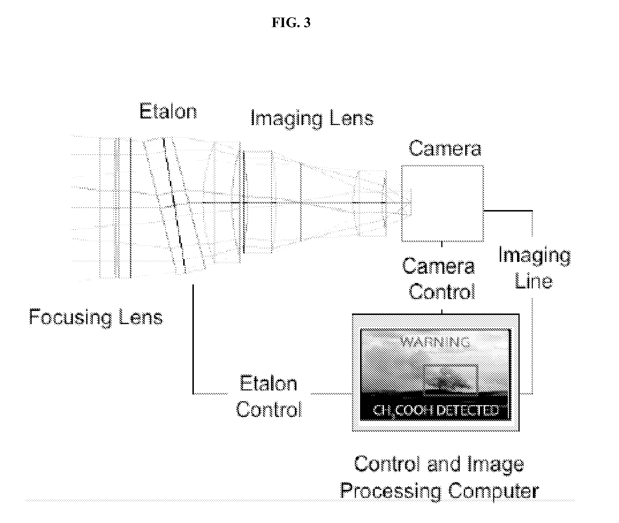
[0067]A conceptual drawing of the SRHE-IS is shown in FIG. 4. The system consists of a Fabry-Perot etalon, an imaging lens, a microbolometer camera, and a computer for spectral and image data post-processing. The proof-of-concept prototype to be built at the beginning of Phase II will use a separate computer for data processing, but future iterations of the design will move the processing to on-board processors within the camera. Our technical approach combines the commercial promise of new low-cost microbolometer cameras with an innovative method to extract super-resolution spectral data from a Fabry-Perot etalon. During the Phase I Option we will investigate existing algorithms for identifying and tagging IR signatures. The SRHE-IS will be lighter, cheaper, and more rugged than existing hyperspectral imaging systems.

[0068]Microbolometer Camera: Coming out of Honeywell in the mid 1980's, a microbolometer responds to thermal changes by producing a corresponding change in its ...


PUM


Abstract

A leak detection and identification system a Fabry-Perot etalon, an imaging lens, a microbolometer camera, and a computer for spectral and image data post-processing, wherein the data peaks are deconvoluted for use thus avoiding the need for bandpass filters.

Description

CROSS REFERENCE TO RELATED APPLICATIONS[0001]This application claims priority to U.S. Provisional Application No. 61 / 144,689, filed Jan. 14, 2009 and incorporated by reference in its entirety.FEDERALLY SPONSORED RESEARCH[0002]Not applicable.REFERENCE TO MICROFICHE APPENDIX[0003]Not applicable.FIELD OF THE INVENTION[0004]A system for inspecting equipment for potential leaks, more specifically, a handheld optical imaging device that detects and identifies leaks in near real time.BACKGROUND OF THE INVENTION[0005]Unintended or “fugitive” gas emissions cost billions of dollars in regulatory fines and damages, pose deadly risks to both workers and people living close to refinery and manufacturing facilities, and are a major contributor to global warming. Leak Detection and Repair (LDAR) is therefore an important component of environmental operations at these facilities to control fugitive emissions.[0006]Sources of leaks include valves, flanges and other connections, pumps and compressors...

Claims


Application Information

Patent Timeline
Patent Type & Authority Applications(United States)
IPC IPC(8): G01F23/284
CPCG01J3/0208G01J3/0264G01J3/027G01J3/26G01J3/2823G01N2021/3531G01J5/0806G01J5/20G01J2005/0077G01M3/38G01J5/08
Inventor PRUET, RICHARD T.COTTON, CHRISTOPHER
Owner INTEGRATED PROCESS RESOURCES
Why Eureka
Try Eureka