Catalyst Coated Membrane (CCM) and Catalyst Film/Layer for Alkaline Membrane Fuel Cells and Methods of Making Same

a catalyst film and fuel cell technology, applied in the field of alkaline membrane fuel cells, can solve the problems of amfc posing a significant challenge, ion conductivity to the water level of an amfc operating amfc poses an additional challenge, and composition and fabrication challenges are more sever

Active Publication Date: 2010-08-26
POCELL TECH LTD
View PDF77 Cites 25 Cited by
  • Summary
  • Abstract
  • Description
  • Claims
  • Application Information

AI Technical Summary

Benefits of technology

[0018]Implementations of the invention may include one or more of the following features and capabilities. The metal nano-powder comprises silver-containing particles.

Problems solved by technology

On the other hand, the AMFC poses a significant challenge derived from its use of OH− ion conducting polymers that demonstrate a more limited ionic conductivity.
In addition, the high sensitivity of this ion conductivity to the water levels of an operating AMFC poses an additional challenge.
Ionic conductivity challenges manifest themselves particularly in the composition and the mode of fabrication of the two catalyst layers that bond to the major surfaces of the membrane electrolyte to form the catalyst-coated membrane (CCM).
These composition and fabrication challenges are more severe with an AMFC design because the effective specific ionic conductivity within the catalyst layer is, typically, an order of magnitude lower than that of the membrane electrolyte.
However, the catalyst structure of FIG. 1 likely has significant drawbacks.
A potential problem with such interfacial crust 24 is that the state of the water level or hydration within an active part of the catalyst layer may be determined by the water transport and water capacity characteristics of these interfacial crusts 24.
An excess of ionomer at an interface of the catalyst layer with the gas diffusion layer will cause high electronic resistance between the gas diffusion layer and the metal catalyst particles, leading potentially to an electronic disconnect.
This objective proves difficult to achieve.
It is understood that the relative low performance of AMFCs with Pt catalysts versus that of Pt-catalyzed PEMFCs is the result of the relatively low ionic (OH−) conductivity in the recast ionomer material used as the bonding agent and ionic conductor in the AMFC catalyst layer.
The performance penalty that results from the lower conductivity of the OH− conducting ionomer is exacerbated further by the low catalyst activity of non-Pt catalysts reported to date.
The low AMFC performance achieved thus far has cast serious doubts on the ability to reduce to practice the central AMFC advantage of using non-Pt catalysts.
In the latter case, the AMFC performance obtained was quite low due to the relatively very low packing density of the catalyst and due to the weight % of cobalt centers, which are not more than 1% of the total weight of the carbon-supported catalyst.
With the conductivity of the recast anion-exchange membrane (AEM) material limited, effective access to a large number of catalyst sites located well inside the thickness of the relatively thick catalyst layer could not be sustained.
The well-known drawback of this alternative is that the degree of dispersion achievable in such metal “blacks,” of unsupported metal particles, is significantly smaller versus the case of carbon-supported catalysts because of the high tendency of the unsupported metal particles to agglomerate.
The repetitive change in ionomer state of hydration causes repetitive polymer dimensional changes and, consequently, will cause delamination along the catalyst / membrane interface unless the interfacial bond is very robust.
This difference in thermo-plasticity makes it impossible to copy directly the catalyst layer / membrane lamination process from the mainstream PEM fuel cell technology.
The carbon support in a cathode catalyst is vulnerable to oxidative loss, particularly near open circuit conditions and under higher cell temperatures.

Method used


Image

  • Catalyst Coated Membrane (CCM) and Catalyst Film/Layer for Alkaline Membrane Fuel Cells and Methods of Making Same
  • Catalyst Coated Membrane (CCM) and Catalyst Film/Layer for Alkaline Membrane Fuel Cells and Methods of Making Same
  • Catalyst Coated Membrane (CCM) and Catalyst Film/Layer for Alkaline Membrane Fuel Cells and Methods of Making Same

Examples


example i

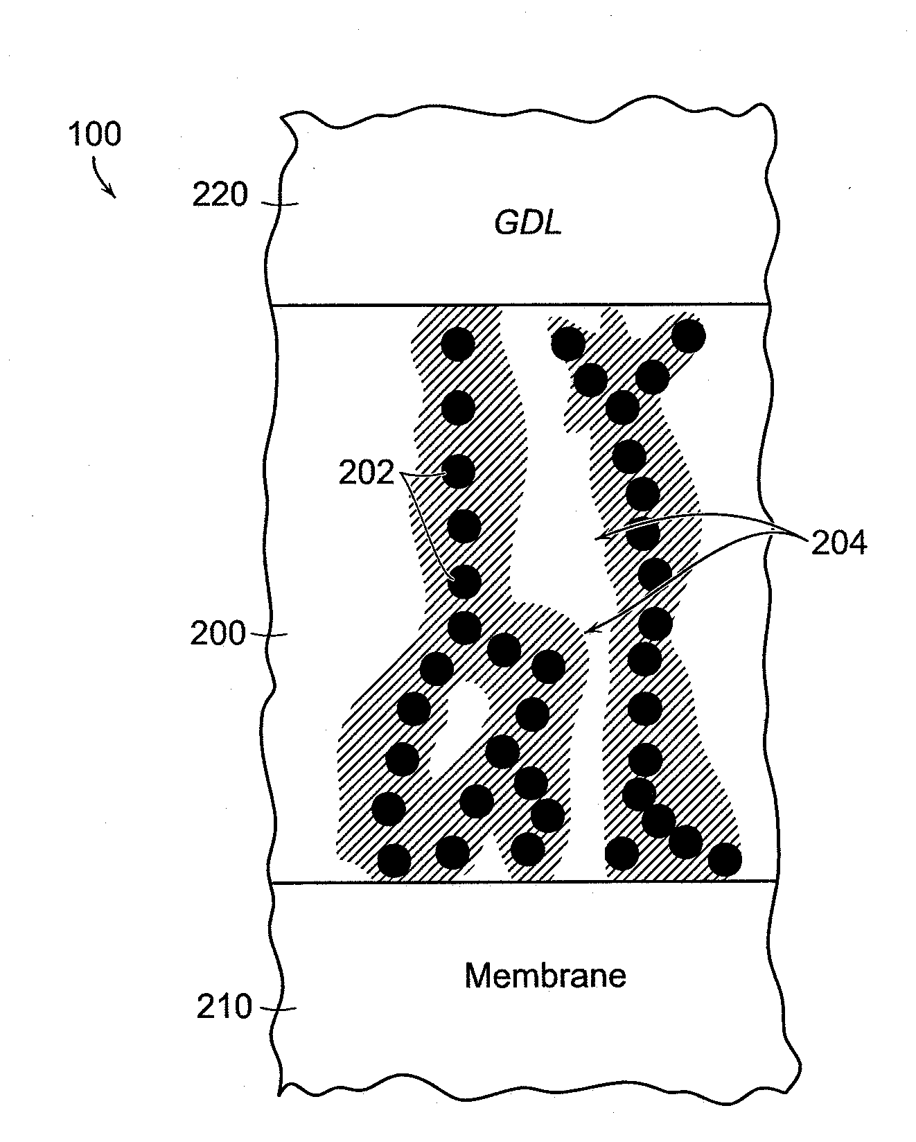
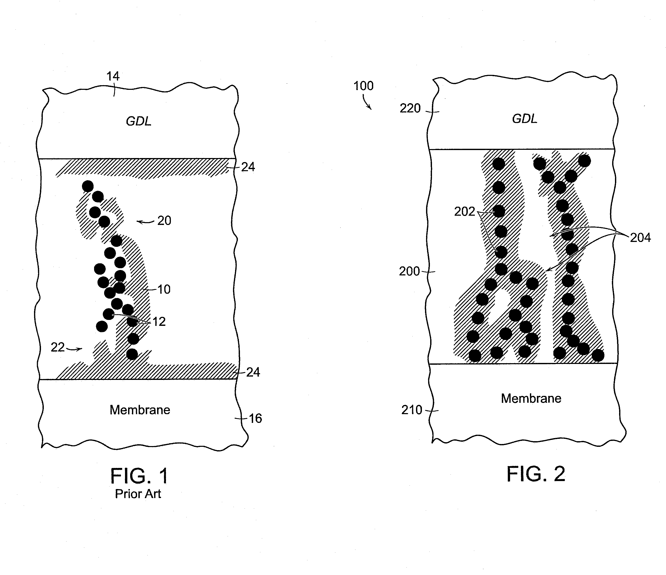
[0051]An exemplary silver-based catalyst formulation or “ink” was prepared by mixing silver nano-particles 202 with a solution of quaternary ammonium-functionalized polymer (QAFP) in certain proportions to form a catalyst ink. In one specific embodiment, the silver nano-particles 202 are mixed with a solution of about 4% to about 5% QAFP in methanol or propanol. The silver nano-powder is added at ten times the weight of the QAFP. Water is added at about 30% of the volume of methanol, and ethylene glycol is added at the level of about 0.5% of the total ink volume. The catalyst ink is ultrasonicated for about 10 minutes, and then mixed, e.g., with a magnetic stirrer, for about one hour. The catalyst ink is ultrasonicated again for about 10 minutes, and then applied, e.g., sprayed or screen-printed, on at least a portion of the cathode side of the membrane 210, or on at least a portion of a Teflon® film blank, with the membrane or blank held down on a vacuum table heated at temperature...

example ii

[0052]Cells prepared by the process described in Example I had CCMs with a cathode Pt catalyst, requiring a volume ratio of ionomer:metal of 4:1 to secure high performance. These cells lost performance at an ever increasing rate under current demand of 0.3-0.4 A / cm2 ending up consistently with a steep drop of the cell voltage down to zero before the end of the second day of continuous operation. Other cells prepared according to Example I had a CCM with a cathode nano-silver catalyst, requiring a volume ratio of ionomer:metal of only 1:1.5 to secure high performance. These cells exhibited a significantly slower, constant rate of power loss at 0.3% the initial power output per hour.

[0053]The steep drop of the cell voltage down to zero was not seen in any of the cells with the nano-silver cathode catalyst over operation times of several hundred hours.

example iii

[0054]CCMs prepared according to Example I with nano silver cathode catalysts were prepared by air-spray application of the ink to a membrane placed on a heated vacuum table and exhibited a constant rate of power loss at about 0.3% of the initial power output per hour. Other CCMs were prepared in the same way and with a similar ink formulation, but using n-propanol as the only solvent (no water added) and applying the ink by screen printing to the membrane at room temperature. The screen-printed CCMs exhibited superior stability, losing only 0.1% of the initial power per hour over 300-400 hours.


PUM

PropertyMeasurementUnit
densityaaaaaaaaaa
diameteraaaaaaaaaa
thicknessaaaaaaaaaa

Abstract

Alkaline membrane fuel cells designed with silver cathode catalysts include a catalyst layer comprising silver metal nano-particles and an anion-conducting ionomer. The silver nano-particles are mixed with a solution of the ionomer to form a catalyst ink that is applied to an alkaline membrane to form an ultra-thin cathode catalyst layer on the membrane surface.

Description

RELATED APPLICATIONS[0001]This application is related to U.S. Provisional Application Ser. No. 61 / 154,622, filed Feb. 23, 2009, to which priority is claimed and the entirety of which is incorporated herein by reference. This application is also related to U.S. patent application Ser. No. 12 / 477,669, filed Jun. 3, 2009, the entirety of which is herein incorporated by reference.FIELD OF THE INVENTION[0002]The invention provides an alkaline membrane fuel cell designed with a silver cathode catalyst.BACKGROUND[0003]Alkaline membrane fuel cells in principle can operate without added liquid electrolyte(s) and thereby rely fully on the ionic conductivity of well-hydrated, anion conducting membranes configured to conduct hydroxide ions (OH−). A liquid electrolyte-free mode of operation has strong advantages in comparison to liquid electrolyte-based fuel cells, as the wide selection of PEM fuel cell technologies employing proton conducting membrane electrolytes shows. Compared to the more es...

Claims


Application Information

Patent Timeline
Patent Type & Authority Applications(United States)
IPC IPC(8): H01M4/90H01M8/10H01M4/88
CPCH01M4/8605H01M4/8663H01M4/881H01M4/8814Y02E60/50H01M4/886H01M4/92H01M8/0291H01M2008/1095H01M4/8835H01M8/0289
Inventor GOTTESFELD, SHIMSHONDEKEL, DARIOSIMAKOV, DAVID STANISLAV
Owner POCELL TECH LTD
Why Eureka
Try Eureka