Optical compensation film, and polarizing plate and liquid crystal display employing the same

a technology of optical compensation film and liquid crystal display, which is applied in the direction of detergent compounding agent, instruments, other domestic articles, etc., can solve the problems of insufficient pasting ability, inability to provide function, and inability to stabilize wavelength dispersion characteristics, so as to improve visibility, reduce contrast, and improve visibility.

Inactive Publication Date: 2010-09-02
KONICA MINOLTA OPTO
View PDF0 Cites 4 Cited by
  • Summary
  • Abstract
  • Description
  • Claims
  • Application Information

AI Technical Summary

Benefits of technology

[0021]An optical compensation film having excellent visibility such as light leakage, color tone unevenness, front contrast and having compatibility of retardation and wave length dispersion properties can be provided by this invention.BEST EMBODIMENT TO PRACTICE THE INVENTION
[0022]The best embodiment to practice the invention is described in detail, however this invention is not restricted thereto.
[0023]The liquid crystal display elements generally have viewing angle characteristics, and there is problem of lowering contrast when observed remote angle from normal angle. It is known that it is effective to provide an optical compensation film (a phase difference film) between the crystal cell and a polarizer to dissolve this problem. It is preferable in general the retardation within a plane (Ro) in the range of 20 to 200 nm, and the retardation in the thickness direction (Rt) in the range of 70 to 400 nm.
[0024]The optical compensation film of this invention is characterized by comprising Polymer (a) manufactured by copolymerizing an ethylenically unsaturated monomer having a partial structure represented by Formula (1) in its molecule with at least one ethylenically unsaturated monomer, and esterified Compound (b) in which all or a part of OH groups in Compound (A) having one furanose or pyranose structure are esterified, or an esterified compound in which all or a part of OH groups in Compound (B), in which 2 to 12 of at least one type of furanose or pyranose structure are bonded, are esterified.
[0025]Further improvement of visibility such as front contrast is expected according to generalization of large format liquid crystal display recently. The inventors studied the above mentioned problem and found that improvement of visibility (light leakage color tone unevenness, front contrast) in addition to compatibility of retardation control and wave length dispersion property are attained by employing Polymer (a) obtained by copolymerizing ethylenically unsaturated monomer having a partial structure represented by Formula (1) in its molecule with at least one ethylenically unsaturated monomer, and accomplished this invention.

Problems solved by technology

However, even if such a technology is used, as an optical compensation film which serves as a polarizing plate protective film, it has an insufficient pasting ability with polyvinyl alcohol being a polarization film, and a polarizing plate protective film consisting of a cellulose ester film has been recognized to be an indispensable optical film in a liquid crystal display even now.
Basically, since cellulose ester film has the circumstances where it has been used as polarizing plate protective film due to its low birefringence characteristic, it may be not easy to provide the function.
In order to acquire a desired retardation value, a technique to add a compound having a retardation increasing effect to a cellulose ester film and to further stretch the film is proposed (Patent Documents 1 and 2), but there are problems that the wavelength dispersion characteristic does no stabilize over time and the permeability of the film is deteriorated by the stretching.
If the wavelength dispersion characteristic is insufficient, phenomena such as light leakage from a polarizing plate (especially light leakage with an elapse of time), uneven color tone of an image on a liquid crystal display and front contrast deterioration occur.

Method used


Image

  • Optical compensation film, and polarizing plate and liquid crystal display employing the same
  • Optical compensation film, and polarizing plate and liquid crystal display employing the same
  • Optical compensation film, and polarizing plate and liquid crystal display employing the same

Examples


example 1

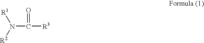
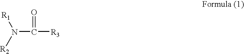
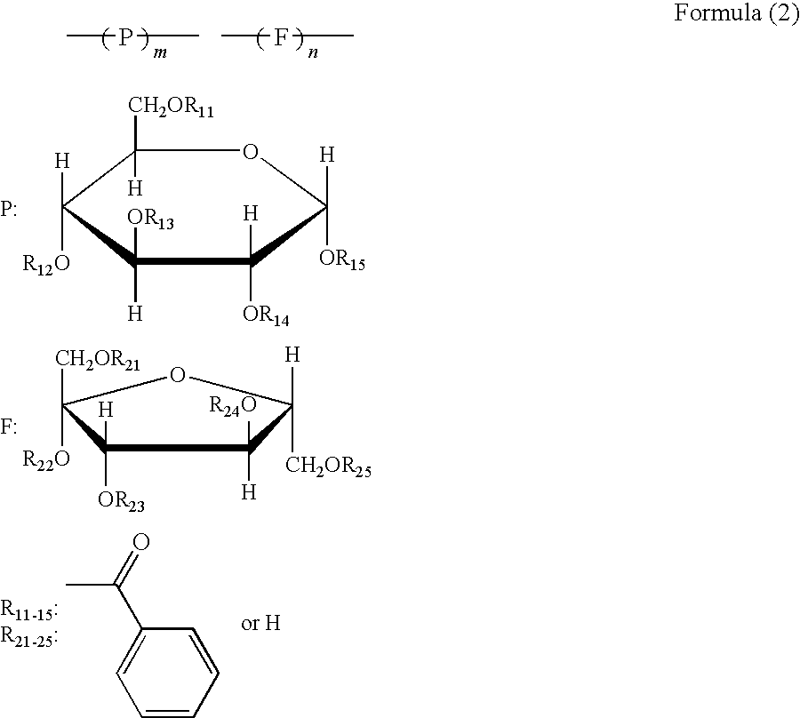
[0230]Cellulose ester, Polymer (a), a compound having a furanose or pyranose structure (Compound (b), sugar ester compound), plasticizers, and UV absorber used in the Examples are listed in Table 1.

TABLE 1Total substitu-Cellulosetion degree ofEsterSubstitution Degree of Acyl groupacyl groupAAcetyl group: 1.9Propionyl group: 0.82.7BAcetyl group: 1.6Propionyl group: 0.92.5CAcetyl group: 1.1Propionyl group: 0.92.0DAcetyl group: 1.2Propionyl group: 1.12.3EAcetyl group: 2.42.4FAcetyl group: 1.3Propionyl group: 1.22.5Sugar EsterCompoundAExemplified Compound 3BExemplified Compound 5CMixture of the same weight ofExemplified Compounds 6 and 7DExemplified Compound 8PlasticizerATriphenyl phosphateBEthylphthalyl ethylglycolateCTrimethylol propanetribenzoateUV AbsorberATINUVIN 326 Ciba Specialty ChemicalsBTINUVIN 109 Ciba Specialty ChemicalsCTINUVIN 171 Ciba Specialty Chemicals

[0231]Polymer (a) used in the Example is described below.

synthesis example 1

[0232]Copolymer AMP-6 of exemplified compound AM-2 and methylmethacrylate was synthesized in accordance the following method.

[0233]Hundred and twenty five grams of polymer raw material composed of 100 parts by weight of monomer mixture of 20% by weight of exemplified compound AM-2 and 80% by weight of methylmethacrylate to which 2.0 parts by weight of peroxy lauroyl, 0.25 parts by weight of n-octylmercaptan and 0.1 parts by weight of stearic alcohol were added, and 250 g of deionized water dissolving preliminarily 0.2 g of 1% aqueous solution of sodium polymethacrylate, 0.05 g of sodium dihydrogen phosphate and 0.15 g of disodium hydrogen phosphate were charged in a flask having stirrer, air was substituted with nitrogen, polymerization was carried out at 70° C. for 3 hours, and then polymerization was further carried out at 100° C. for 1 hour. Bead form of copolymer AMP-6 was obtained through cooling, filtration, washing and drying processes after completion of polymerization. The ...

synthesis example 2

[0235]Copolymer AMP-7 of exemplified compound AM-2 and methylacrylate was synthesized in accordance the following method.

[0236]Into 100 ml of toluene, 10 g of monomer mixture of 50 weight parts of AM-2 and 50 weight parts of methyl methacrylate was added, then 0.1 g of azobisisobutyronitrile was added. Temperature was raised up to 80° C. and polymerization was carried out for 5 hours in nitrogen atmosphere. After removing 70 ml of toluene by evaporation under reduce pressure, the content was dripped far excess amount of methanol. Deposited precipitation was subjected to filtration, washing, and drying processes, and powder copolymer AMP-7 was obtained. The copolymer was confirmed to have an weight average molecular weight of 30,000 and Mw / Mn of 3.0 by GPC analysis employing standard polystyrene.

[0237]Thus obtained copolymer was confirmed as a copolymer of the exemplified compound AM-2 and methylacrylate by NMR spectrum. Composition content of AM-2 / methylacrylate was approximately 50...


PUM

PropertyMeasurementUnit
thicknessaaaaaaaaaa
refractive indexaaaaaaaaaa
wavelengthaaaaaaaaaa

Abstract

The present invention provides an optical compensation film, which has excellent visibility such as light leakage, uneven color tone and front contrast, and can simultaneously realize retardation and wavelength dispersion. The optical compensation film is characterized by containing a cellulose ester, the following polymer (a), and the following compound (b). (a) A polymer produced by copolymerizing an ethylenically unsaturated monomer having in its molecule a partial structure represented by Formula (1) with at least one ethylenically unsaturated monomer. (b) An esterified compound produced by esterifying all or a part of OH groups in a compound (A) having one furanose structure or one pyranose structure, or an esterified compound produced by esterifying all of or a part of OH groups in a compound (B) containing nor less than 2 and not more than 12 structures of at least one of a furanose structure or a pyranose structure.

Description

[0001]This is a U.S. National Phase Application under 35 U.S.C. 371 of International Application PCT / TP2008 / 069447, filed on Oct. 27, 2008.[0002]This application claims the priority of Japanese application No. 2007-287153, filed Nov. 5, 2007, the entire content of which is hereby incorporated by reference.TECHNICAL HELD[0003]The present invention relates to an optical compensation film used for a liquid crystal display, in particular, relates in detail to an optical compensation film which is excellent in visibility (light leakage, color tone unevenness, front contrast), and compatible to both retardation and wavelength dispersion characteristic.TECHNICAL BACKGROUND[0004]A cellulose ester film, a polycarbonate film, a poly cyclic olefin film, and so on are widely used as an optical film for liquid crystal displays.[0005]Since the transparency of a cellulose ester film is optically high and also its birefringence is low, it has been mainly used as a protective film (hereinafter; refe...

Claims


Application Information

Patent Timeline
Patent Type & Authority Applications(United States)
IPC IPC(8): C08K5/10C09K19/00
CPCC08J5/18Y10T428/10C08K5/151C08L1/10C08L1/14G02B1/04G02B5/3083C08J2339/04Y10T428/1041C08L1/04B29D11/00788C08L33/14C09K2323/031C09K2323/00
Inventor SERA, TAKASHI
Owner KONICA MINOLTA OPTO
Why Eureka
Try Eureka