[0011]An object of the invention is to provide a monolithic photo-electrochemical system provided with a plurality of cells arranged on a common substrate, which monolithic photo-electrochemical system has improved efficiency in relation to prior art systems without imposing stricter requirements on the production processes, thereby enabling cost effective production of such electrochemical systems.
[0019]When a photo-electrochemical system is installed outdoors for the purpose of conversion of light to
electric energy, it is likely that parts of certain solar cells, arranged on a common substrate will temporarily be positioned in the shade while the remaining parts are positioned under direct
sunlight. As an effect of the inventor's observation that the open-circuit
voltage is constant or only slightly decreases when a
cell is partially or completely shaded, parallel-connections of cells should lead to less energy losses in the situation of partial shading of a monolithic photo-electrochemical system with an array of cells on the same substrate, in comparison to serial-connected cells. This has lead to experiments by the inventor verifying that, in the case of partial shading of one or several cells in an array of connected cells, more of the generated energy by the individual cells will be available as output from the system of connected cells when the cells are arranged in parallel in comparison to the case where the cells are connected in series.
[0020]Furthermore, in the event of a single
cell or some of the cells in a photo-electrochemical system, where the cells are serial-connected on a common substrate, which is used as a device for conversion of light into
electric energy, is at least partially positioned in the shade or if one or some of the cells have lower short-circuit current than the others, due to differences from the origin of the cells or due to different
ageing of the cells, the current will pass through this or these cells under
reverse bias, that is negative polarity, when the system is operated at currents higher than the short-circuit current of the this or these cells cell. This may lead to degradation of the cell and will certainly lead to reduced efficiency of the system since energy is dissipated in cells under
reverse bias. In a monolithic photo-electrochemical system where the cells are connected in parallel, the risk for occurrence of this problem is much smaller due to three observations of the inventor: 1) the open-circuit
voltage of a partly shaded monolithic photo-
electrochemical cell remains constant or decreases slightly in relation to the non-shaded situation, 2) the open-circuit
voltage is approximately constant for cells manufactured on a common substrate, and 3) the open-circuit voltages for cells manufactured on the same substrate evolve much more evenly than the short-circuit currents. As a consequence of this, cells operating at
reverse bias due to partial shading can be avoided much more efficient when the cells are arranged in parallel in comparison to the case where the cells are connected in series, resulting in
higher power output and longer life of the system.
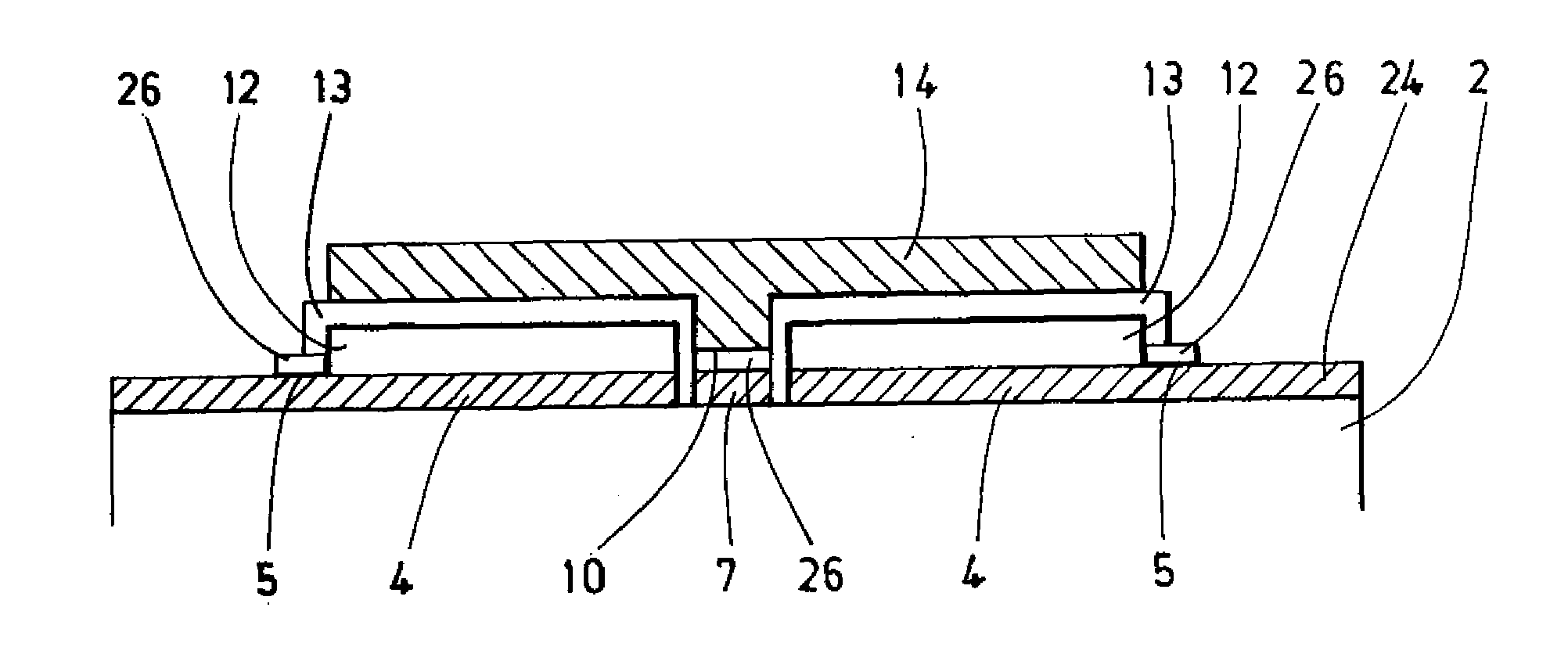
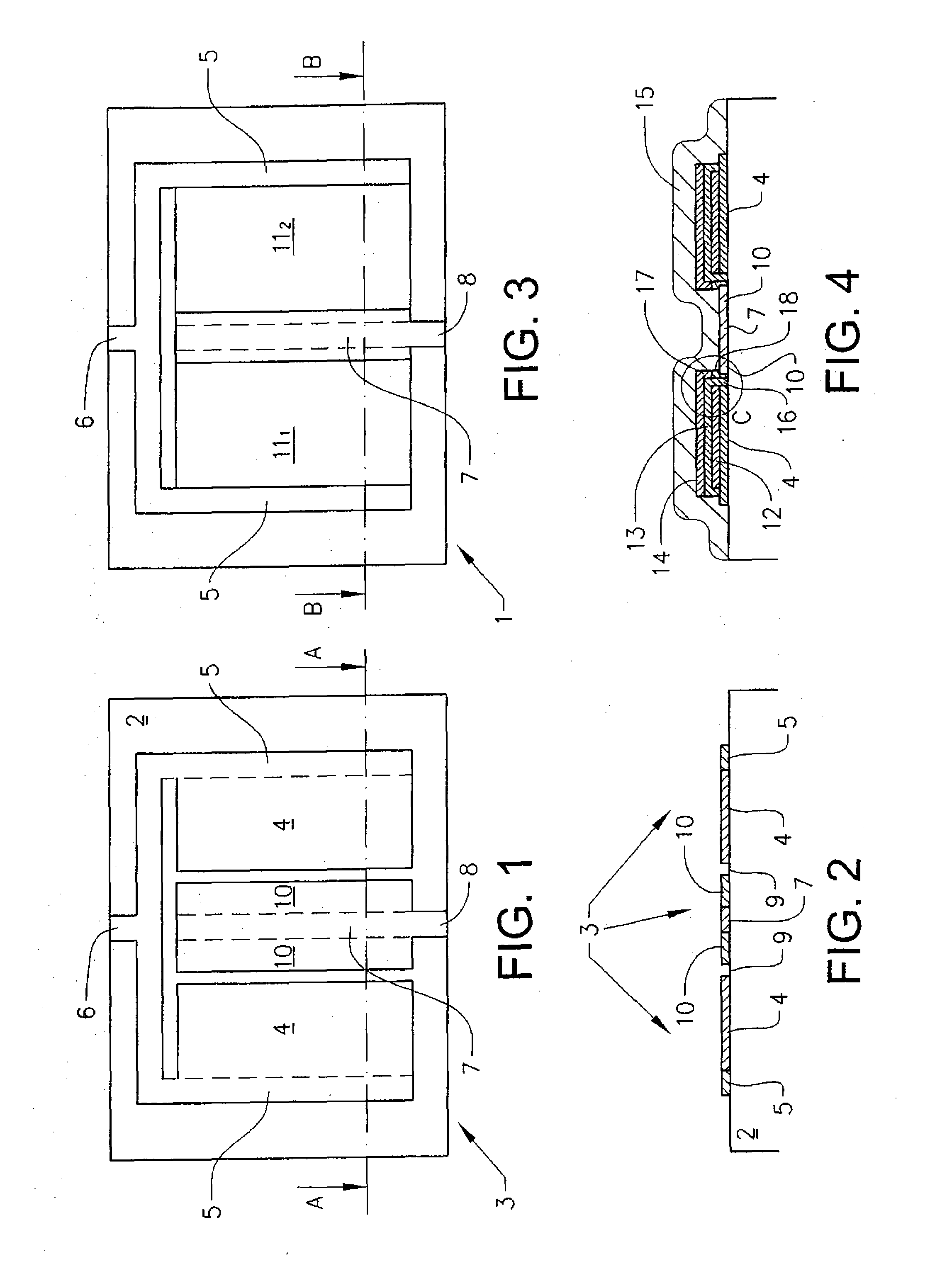
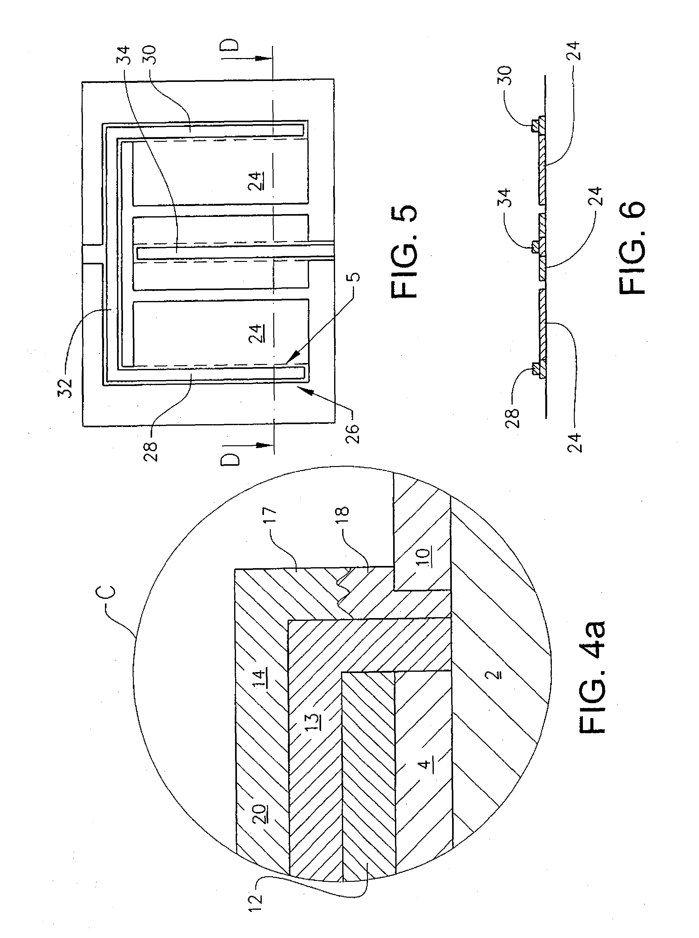
[0023]By
sintering the
working electrode and the counter electrode in two different
sintering processes, it is possible to optimise the
sintering processes for respective electrode. The sintering process for the working electrode, which is preferably formed by a TiO2 composition is preferably made at a temperature of approximately 450° C., while the sintering process for the counter electrode, which is preferably made of carbon is sintered at approximately 390° C. By sintering the counter electrode of carbon at a lower temperature, a significantly lower resistance of the counter electrode is obtained. This results in less energy losses caused by the
electron transport through the counter electrode in a monolithic photo-
electrochemical cell and thus in higher cell efficiencies.
[0024]In a preferred embodiment of the invention, the counter electrode is deposited on the substrate in a first and a second process step where a
contact layer for the counter electrode is applied in the first step and the remaining part of the counter electrode in a second step. By introducing a
contact layer, increased adherence between the counter electrode and the contact path and / or substrate may be achieved without negative effect on the
conductivity of the remaining part of the counter electrode.

