Ultra-High Strength, Corrosion Resistant Wire, a Method of Making Same, and a Method of Using Same

a high-strength, corrosion-resistant wire technology, applied in the direction of layered products, transportation and packaging, chemical instruments and processes, etc., can solve the problems of alloy lack of ductility to resist breaking in a standard wire-wrap test, and users of such cables are now demanding even higher strength levels for this application, so as to reduce the cross-sectional area

Inactive Publication Date: 2010-09-16
FRANK RICHARD B +1
View PDF13 Cites 5 Cited by
  • Summary
  • Abstract
  • Description
  • Claims
  • Application Information

AI Technical Summary

Benefits of technology

[0009]In accordance with a further aspect of the present invention, there is provided a wire formed from a high strength, corrosion resistant alloy having the following composition in weight percent, about
[0010]Here and throughout this specification the following definitions apply unless otherwise indicated. The term “percent”

Problems solved by technology

However, the users of such cables are now demanding even higher strength levels for this application.
However, when that alloy is processed to pr

Method used


Image

  • Ultra-High Strength, Corrosion Resistant Wire, a Method of Making Same, and a Method of Using Same

Examples


working examples

Example 1

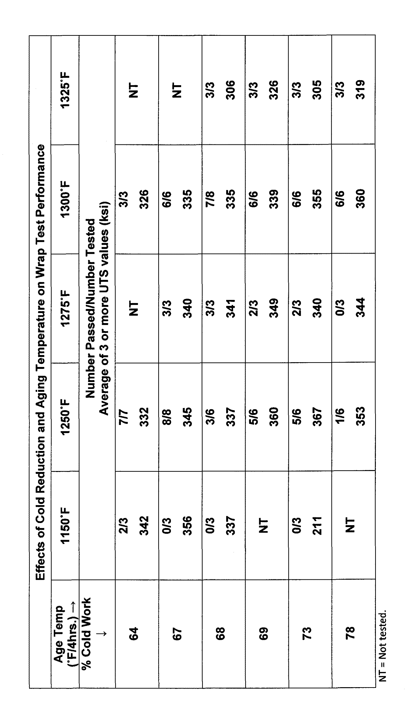
[0015]Experimental trials were performed using 0.0565 in rd. wire from a triple melted heat having the weight percent composition set forth in Table I below. Triple melting is a known technique that includes the steps of vacuum induction melting (VIM), followed by electroslag remelting (ESR), and then vacuum arc remelting (VAR). The wire was annealed at subatmospheric pressure at 1800° F. for 90 minutes and then quenched in argon gas. The grain size of the annealed wire was about ASTM size 6-8. Wire samples cut from the annealed coils were cold drawn to 50%, 55%, 60%, 64%, and 67% reductions in cross-sectional area (R.C.S.A.) to provide wire diameters of 0.040 in., 0.038 in., 0.036 in., 0.034 in., and 0.032 in., respectively. Cold drawing is performed with the wire at room (ambient) temperature. The wire samples were then aged at temperatures in the range of 1050° F.-1250° F. in argon-filled SEN / PAK® heat treating containers. Fine wire tensile tests and wrap tests were cond...

example 2

[0019]In a second set of tests, wire from another production heat of the UNS R00035 alloy was processed into fine wire. The heat chemistry of the additional wire material (Example 2) is presented in Table I above. The wire was cold drawn 68% R.C.S.A. to 0.031″ in diameter. The cold drawn wire was aged at various combinations of temperature and time as shown in Table V. Also, set forth in Table V are the results of room temperature tensile and wrap tests including the 0.2% offset yield strength (0.2% Y.S.) and the ultimate tensile strength (U.T.S.) in ksi, the percent elongation (% El.), the percent reduction in area (% R.A.), together with an indication whether the wire passed or failed the wrap test (Wrap Test). The aging heat treatment given to each test sample is shown in the column labeled “Age Treatment”. Some of the wire samples were given underaging heat treatments at 600° F. and 750° F., respectively, for 4 hours. The underaged samples were evaluated to determine if the desi...


PUM

PropertyMeasurementUnit
Temperatureaaaaaaaaaa

Abstract

A method of making steel wire is described that includes the step of forming a length of wire from a high strength, corrosion resistant alloy. The alloy preferably has the following composition in weight percent.

Carbon
0.03
max.
Manganese
0.15
max.
Silicon
0.15
max.
Phosphorus
0.015
max.
Sulfur
0.010
max.
Chromium
19.00-21.00
Nickel
33.00-37.00
Molybdenum
 9.00-10.50
Titanium
1.00
max.
Boron
0.010
max.
Iron
1.00
max.
The balance of the alloy is cobalt and usual impurities. The wire is annealed at a combination of temperature and time effective to provide a grain size of about ASTM 6 or finer. The annealed wire is then drawn such that the cross-sectional area of the wire is reduced by about 50 to 80%. The as-drawn wire is then heat treated at a second combination of temperature and time effective to provide the wire with high strength and sufficient ductility that when the wire is wrapped to provide a coil having an inside diameter substantially commensurate with the diameter of the wire and then unwrapped it does not crack or break.

Description

CROSS-REFERENCE TO RELATED APPLICATIONS[0001]This application claims the benefit of U.S. Provisional Application No. 61 / 159,577, filed Mar. 12, 2009, the entirety of which is incorporated herein by reference.BACKGROUND OF THE INVENTION[0002]1. Field of the Invention[0003]This invention generally relates to fine gauge, high strength wire, and in particular, it relates to a wire product that provides a unique combination of very high strength, excellent ductility, and good corrosion resistance for use in armored cable.[0004]2. Description of the Related Art[0005]Armored communication cable has been used for transmission of communication and control signals to equipment operating in oil wells, particularly in deep sour gas wells. One type of armored cable for the oil well application is described in U.S. Pat. No. 6,255,592, the entire disclosure of which is incorporated herein by reference. Typically, the armor portion of such cables is made from steel wire that contains a medium to hi...

Claims


Application Information

Patent Timeline
IPC IPC(8): C22F1/00C22C30/00
CPCC22C19/055C22C19/056C22C19/07Y10T428/2925C22F1/10B32B15/02H05K9/0098C22C30/00
Inventor FRANK, RICHARD B.BURLESON, LYNDON W.
Owner FRANK RICHARD B
Why Eureka
Try Eureka