
Solid-state imaging device, method for driving solid-state imaging device, and electronic apparatus

a solid-state imaging and imaging device technology, applied in the direction of radio frequency controlled devices, instruments, television systems, etc., can solve the problems of reducing the conversion efficiency of charge-to-voltage, not suitable for pixel size reduction, and not suitable for miniaturization, so as to prolong the charge retention time of the charge storage capacitor, improve noise immunity, and reduce the conversion efficiency of the fd part.

Active Publication Date: 2010-09-16
SONY CORP
View PDF5 Cites 39 Cited by
  • Summary
  • Abstract
  • Description
  • Claims
  • Application Information

AI Technical Summary

Benefits of technology

[0011]In the related art technique described in Japanese Unexamined Patent Application Publication No. 2005-65074, two reset transistors each for resetting a different one of the two charge storage capacitors are further necessary. This increases the number of components that are to be integrated in one pixel, thereby making high integration difficult. Moreover, two reset signal lines are necessary at least for pixel reset, which complicates the structures of peripheral driving circuits for driving pixels.
[0012]It is therefore desirable to provide a solid-state imaging device that achieves high integration without a decrease in conversion efficiency when converting a charge to a voltage, a method for driving the solid-state imaging device, and an electronic apparatus including the solid-state imaging device.
[0014]In the solid-state imaging device with the above structure, since the charging transistor is interposed between the FD part and the charge storage capacitor having a global shutter function, the charge storage capacitor is not connected in parallel with the capacitance of the FD part. Therefore, the insertion of the charge storage capacitor does not cause a significant change in capacitance value of the FD part. This makes it possible to satisfy both the charge retention time of the charge storage capacitor and the conversion efficiency of the FD part which are in a tradeoff relationship. In detail, by setting a large capacitance value of the charge storage capacitor, an extended charge retention time of the charge storage capacitor and improved noise immunity can be attained without a decrease in conversion efficiency of the FD part. Moreover, the global shutter function is available with a small number of components, where only one charge storage capacitor and two transistors (the charging transistor and the second reset transistor) are added to each unit pixel.
[0015]According to the embodiment of the present invention, it is possible to satisfy both the charge retention time of the charge storage capacitor and the conversion efficiency of the FD part which are in a tradeoff relationship, and also achieve the global shutter function with a small number of components. Hence, high integration can be attained without a decrease in conversion efficiency of the FD part.

Problems solved by technology

However, the large capacitance value of the charge storage capacitor causes an increase in capacitance of the floating diffusion part, which results in a decrease in charge-to-voltage conversion efficiency.
Hence, the related art technique described in Japanese Unexamined Patent Application Publication No. 11-177076 is not suitable for pixel size reduction.
Therefore, the related art technique described in Japanese Unexamined Patent Application Publication No. 11-177076 is not suitable for miniaturization.
Besides, since KTC noise upon reset may not be removed, it is difficult to suppress pixel-specific fixed pattern noise.
This increases the number of components that are to be integrated in one pixel, thereby making high integration difficult.
Moreover, two reset signal lines are necessary at least for pixel reset, which complicates the structures of peripheral driving circuits for driving pixels.

Method used


Image

  • Solid-state imaging device, method for driving solid-state imaging device, and electronic apparatus
  • Solid-state imaging device, method for driving solid-state imaging device, and electronic apparatus
  • Solid-state imaging device, method for driving solid-state imaging device, and electronic apparatus

Examples


embodiment

2. Embodiment

Circuit Structure

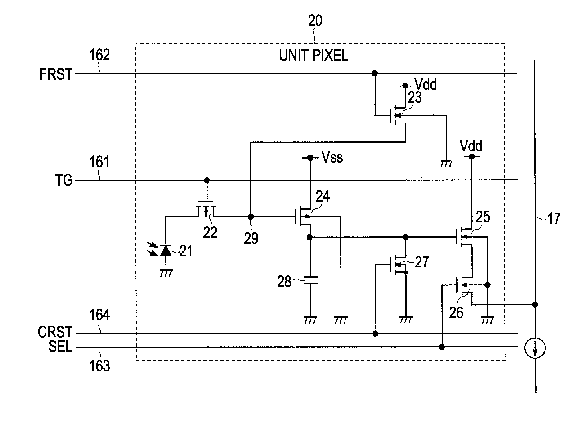
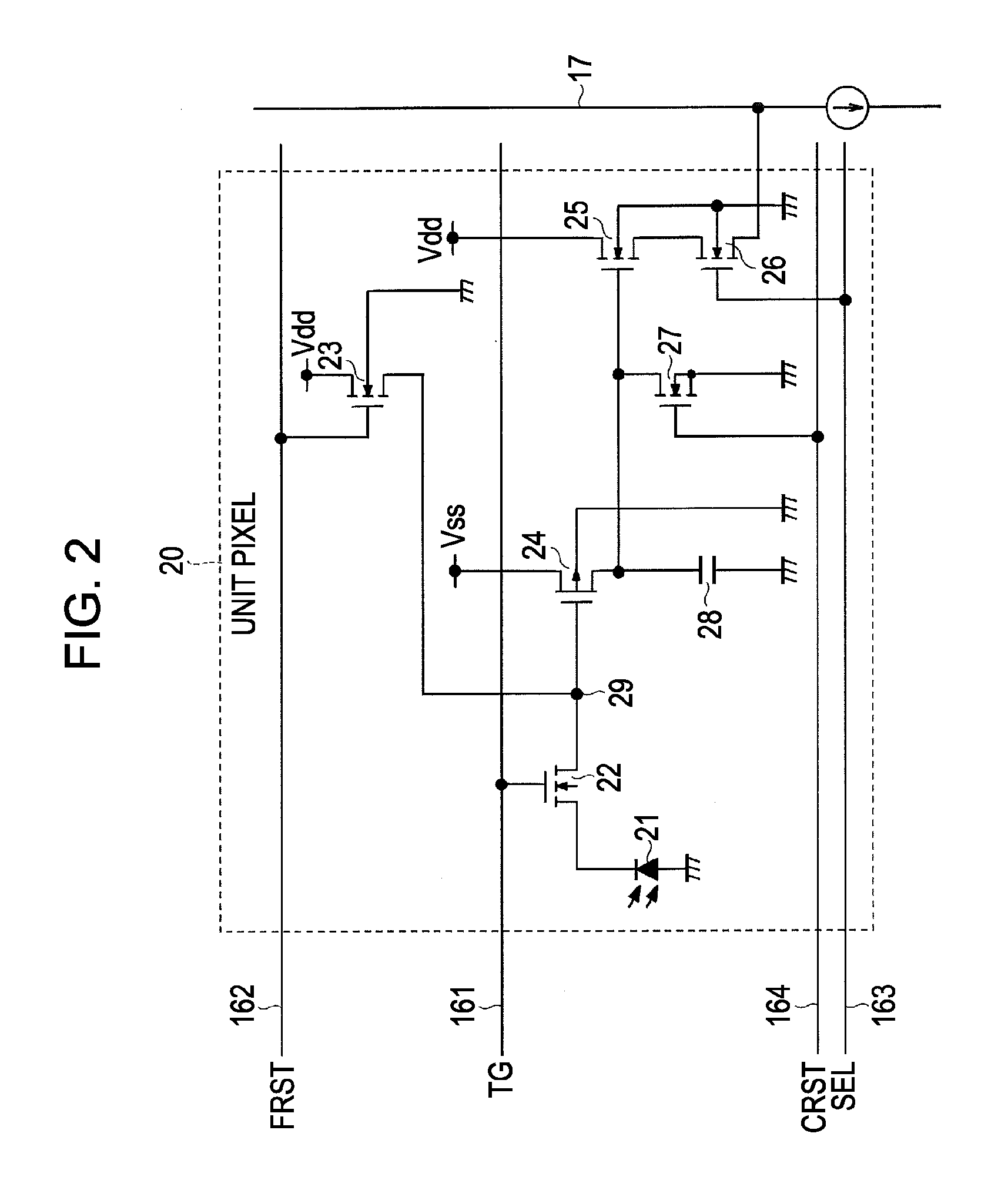
[0044]FIG. 2 is a circuit diagram showing a circuit structure of the unit pixel 20 according to an embodiment. As shown in FIG. 2, the unit pixel 20 according to the embodiment includes, for example, six transistors 22 to 27 and one capacitor 28, in addition to, for example, a photodiode 21 which is a photoelectric conversion part. The capacitor 28 is the charge storage capacitor for achieving the global shutter function.

[0045]For instance, N-channel MOS transistors are used as the transistors 22, 23, and 25 to 27 and a depression type MOS transistor is used as the transistor 24. However, the conductivity type combination of the transistors 22 to 27 exemplified here is merely an example, and the conductivity type combination is not limited to such.

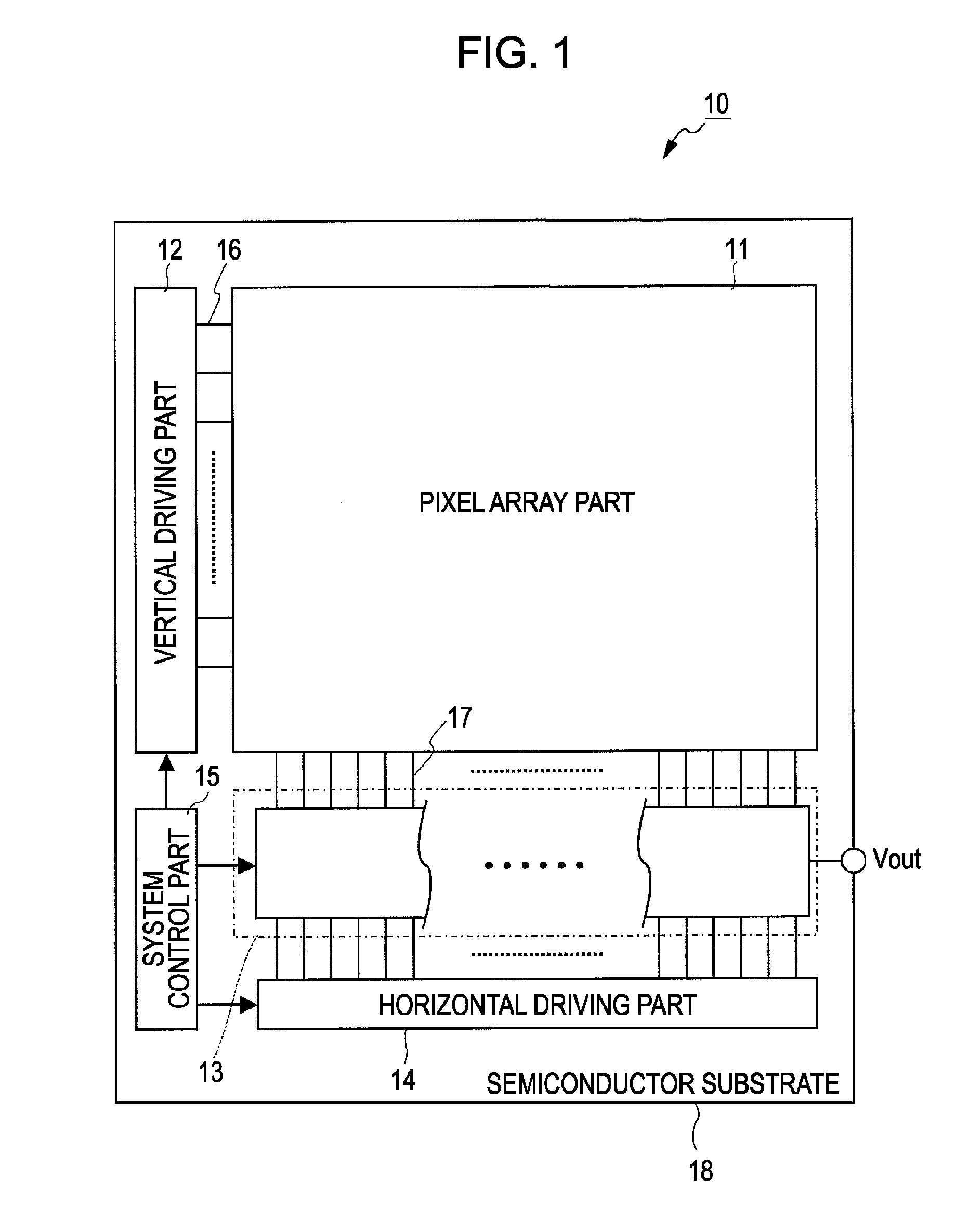
[0046]For this unit pixel 20, for example, four pixel driving lines of a transfer line 161, a first reset line 162, a selection line 163, and a second reset line 164 are wired as the pixel driving line 16 so a...


PUM


Abstract

A solid-state imaging device having unit pixels arranged therein is provided, each unit pixel including: a transfer transistor configured to transfer a charge from a photoelectric conversion part to a floating diffusion part; a first reset transistor configured to reset the floating diffusion part; a charge storage capacitor; a charging transistor configured to charge the charge storage capacitor by a current corresponding to a charge in the floating diffusion part; a second reset transistor configured to reset the charge storage capacitor; an amplifying transistor configured to output an electric signal corresponding to a charge in the charge storage capacitor; and a selection transistor configured to selectively cause the amplifying transistor to be in an operation state.

Description

BACKGROUND OF THE INVENTION[0001]1. Field of the Invention[0002]The present invention relates to a solid-state imaging device, a method for driving the solid-state imaging device, and an electronic apparatus. The present invention particularly relates to an X-Y address type solid-state imaging device having a global shutter function, a method for driving the solid-state imaging device, and an electronic apparatus including the solid-state imaging device.[0003]2. Description of the Related Art[0004]There are two main types of solid-state imaging devices: an X-Y address type solid-state imaging device such as a CMOS (complementary metal oxide semiconductor) image sensor; and a charge transfer type solid-state imaging device such as a CCD (charge coupled device) image sensor. The CMOS image sensor is capable of random access to pixel signals, and also has advantages of fast pixel signal reading and low power consumption as compared with the CCD image sensor.[0005]Most CMOS image sensor...

Claims


Application Information

Patent Timeline
IPC IPC(8): H01L27/148H01L31/09H01L27/146H04N5/335H04N5/353H04N5/369H04N5/374H04N5/376
CPCH01L27/14609H01L27/14621H01L27/14627H01L27/14636H01L27/14641H04N5/353H04N5/37457H01L27/1464H01L27/14643H04N25/778H04N25/532H04N25/53
Inventor WATANABE, KAZUFUMI
Owner SONY CORP
Learn More