
Actuator on the basis of geometrically anisotropic nanoparticles

a nanoparticle, geometric anisotropic technology, applied in the direction of piezoelectric/electrostrictive device details, generators/motors, electrostatic generators/motors, etc., can solve the problems of changing the shape of nanoparticles and the lattice spacing, and achieve the effect of optimizing the utilization of effects and significantly increasing actuator rigidity

Inactive Publication Date: 2010-09-23
KERNFORSCHUNGSZENTRUM KARLSRUHE GMBH
View PDF4 Cites 7 Cited by
  • Summary
  • Abstract
  • Description
  • Claims
  • Application Information

AI Technical Summary

Benefits of technology

[0006]The specific electric resistance of metallic and semiconductive CNTs (depending on the orientation of the hexagonal structure of the graphite lattice relative to the tube axis=helicity) differ significantly from each other. Metallic CNTs have, with ideal observation, practically no specific electrical resistance, since the electrons are conducted in the nanotube almost ballistically, that is, without stray losses. However, if such a CNT is contacted by metal contacts, a transits resistance in the kΩ range develops at each contact point. In semicon-conductive CNTs, the specific resistance depends on the voltage applied, the resistance in the range of about −0.5 V to 0.5 V being several MΩ depending on the contacting. The current / voltage characteristic line is nonlinear in the range of about −1V to 1V. By the application of a gate voltage via a third electrode to a semi-conductive CNT, like in a field effect transistor, this non-linearity of the characteristic line can be suppressed and the specific resistance can be reduced.
[0016]high modulus of elasticity of the active elements, high actuator forces can be achieved as a result;
[0026]Such actuators have, with the bucky-paper used, a resiliency which is extremely high in comparison with the individual CNTs (higher by about a factor 2200). Such an actor cannot be highly stressed mechanically. Consequently, also a strong dependency of the actuator expansion on the forces effective on the actuator can be expected and, in principle, also a non-linear correlation between tension and expansion and the occurrence of hysteresis of the expansion behavior. Furthermore, the access of the electrolyte ions to the CNTs in the interior of the Bucky paper in comparison with the outer CNTs is first delayed which, in connection with the low electrical conductivity of Bucky-paper, limits the maximally possible deflection frequencies of the actuators and also results in a higher heat loss and a lower actuator expansion. In addition, restructuring and settling processes in the relative loose Bucky paper structure and consequently, an increase in cycle-dependent degradation effects of the actuators can be expected.
[0030]As nanoparticles, basically all materials are suitable on whose surface a double layer is formed in an electrolyte. Such a double layer causes a change of the lattice spacing and as a result a change in the shape of the nanoparticles. An influence can be observed basically in all types of connections. The special advantage of CNTs or other nanotubes resides in the maximally possible ratio of surface (with double layer) to volume and consequently, in an optimal utilization of the effect mentioned earlier.
[0031]A further essential detail feature of the invention resides in the material interconnection of the nanoparticles and the webs. The interconnection is formed from a reaction product of the web-side and particle-side materials wherein those materials as well as the reaction product are electrically conductive. Furthermore, each of the nanoparticles is connected to at least two webs whereby the actuator rigidity can be significantly increased.
[0043]particularly high actuator rigidity and, consequently, low dependency of the expansion on the forces effective on the actuator

Problems solved by technology

Such a double layer causes a change of the lattice spacing and as a result a change in the shape of the nanoparticles.

Method used


Image

  • Actuator on the basis of geometrically anisotropic nanoparticles
  • Actuator on the basis of geometrically anisotropic nanoparticles
  • Actuator on the basis of geometrically anisotropic nanoparticles

Examples


Embodiment Construction

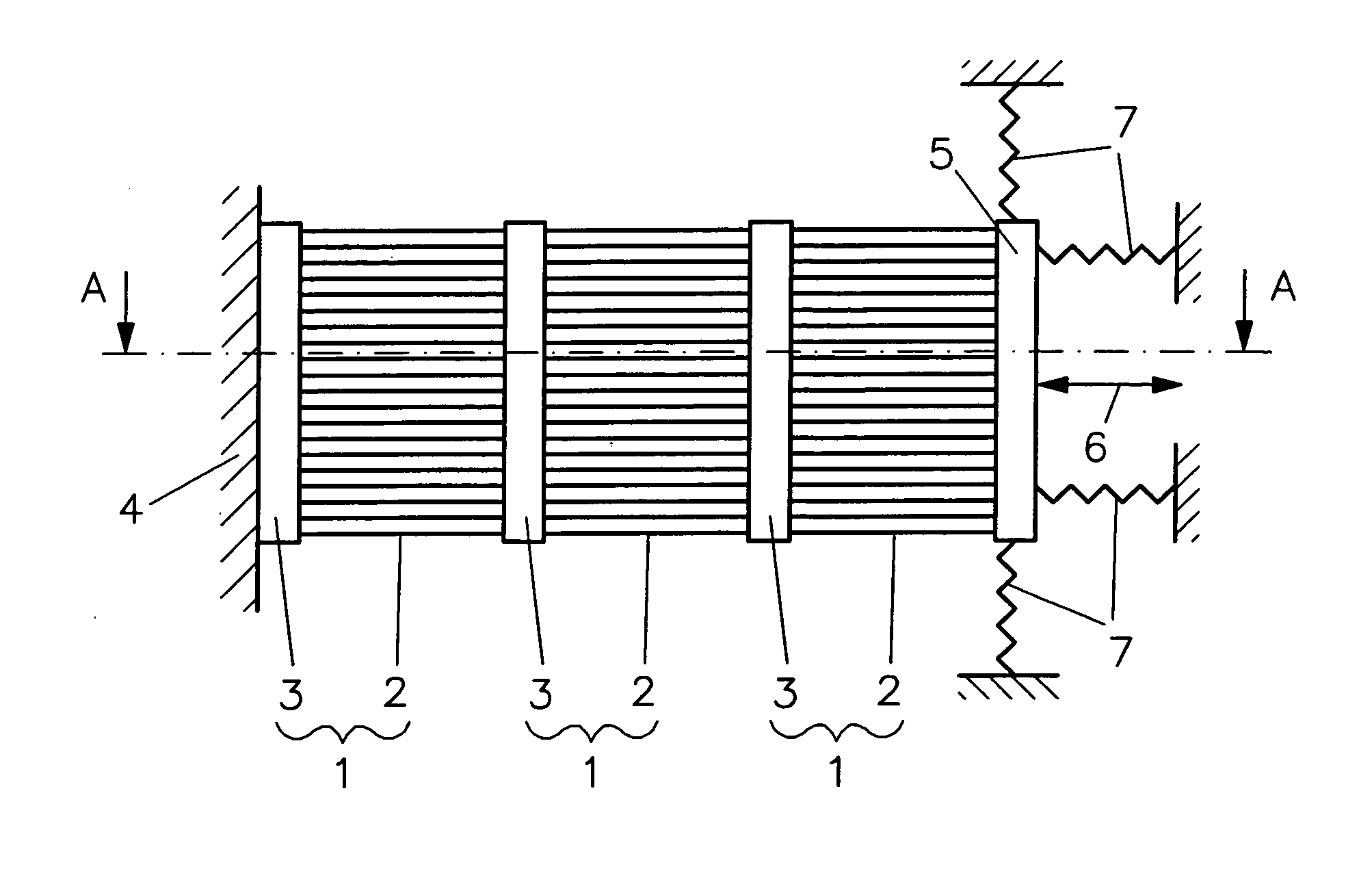
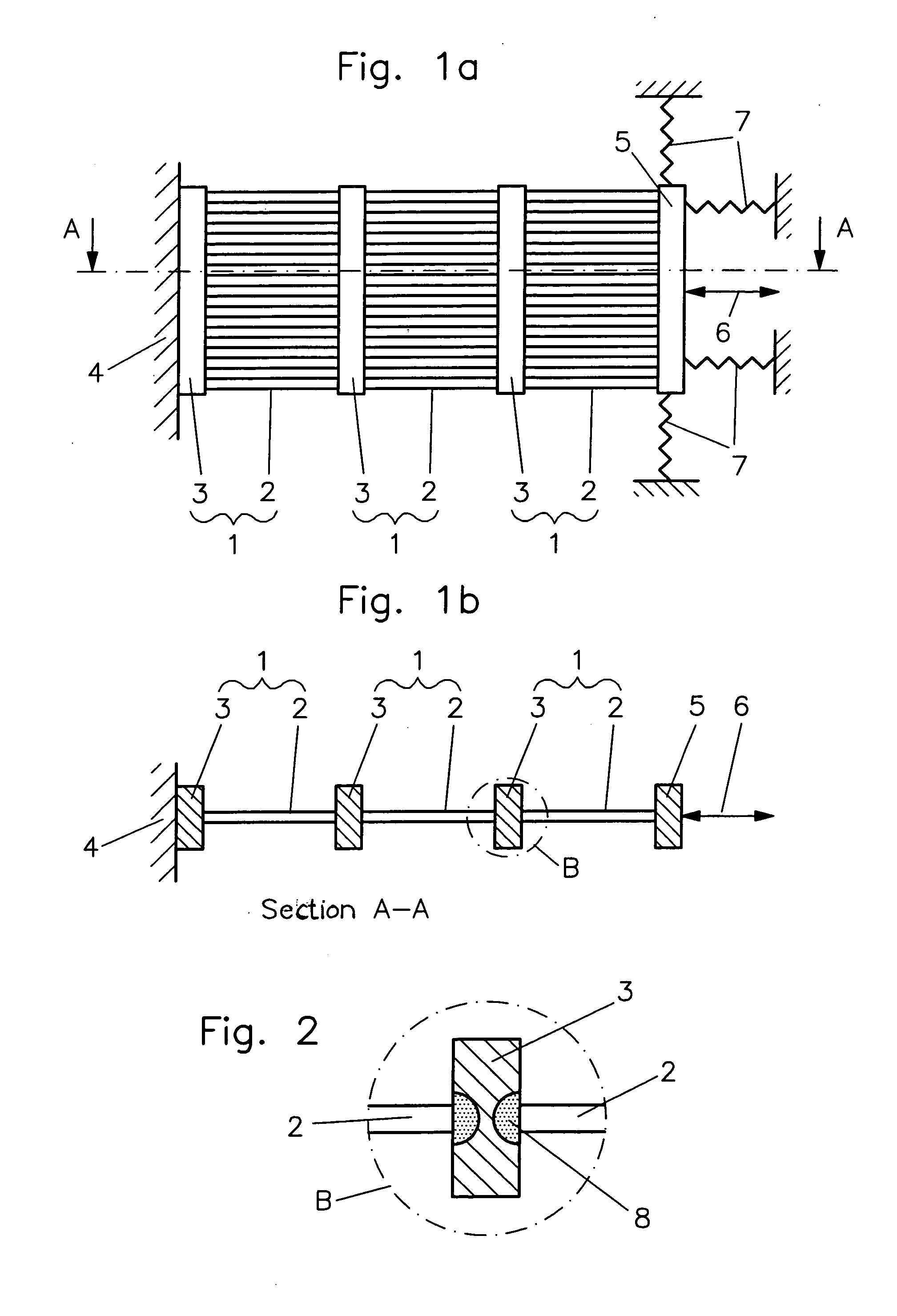
[0052]The core part of the invention, that is, the active electrode, is shown in FIGS. 1a and 1b wherein FIG. 1b is a cross-sectional view of the active electrode taken along line A-A of FIG. 1a. The active electrode consists of several actuator layers 1 comprising a plurality of CNTs 2 arranged parallel to one another and webs 3 arranged orthogonally to the CNTs. In the embodiment shown, the active electrode is connected with one end by means of a web to a solid support structure 4 and, with its free end, which is preferably also formed by a web in the form of an end member 5, executes the actuator actuation 6. Furthermore, FIG. 1 shows the elastic elements 7 for pretensioning a compression actuator and for guiding the webs 3.

[0053]The CNTs are arranged in the active electrode of the shown embodiment not in clusters but preferably in a plane parallel to one another (see FIG. 1b). In this way, uninhibited access of ions of the electrolyte is ensured, which substantially reduces poss...


PUM


Abstract

In an actuator including at least one active electrode disposed in an electrolyte and comprising at least two webs of an electrically conductive material with a plurality of geometrically anisotropic nanoparticles disposed thereon and oriented uni-directionally in a preferential direction with an electrically conductive connection between the nanoparticles and the webs and a potential difference with respect to ground can be applied to the active electrode by a voltage or current source, the nanoparticles are connected in each case to two webs and the connections are material-interlocking.

Description

[0001]This is a continuation-in-part application of international patent application PCT / EP2005 / 004053 filed Apr. 16, 2005 and claiming the priority of German application 10 2004 025 603.9 filed May 25, 2004[0002]The present application resides in an actuator, particularly a translation or bending actuator, on the basis of electrically and mechanically contacted geometrically anisotropic nanoparticles, particularly small tubes or fibers with diameters in the nano meter area, for example carbon nano-tubes.[0003]Actuators serve the direct conversion of electrical energy into a mechanical positioning movement and, as a result, form essential components for many technical systems, particularly in robotics or in switching devices.[0004]Actuators of the type mentioned above are based on so-called electro-mechanical actuation materials. In such materials, a change of the shape or of the mechanical properties is in direct interaction with an applied electrical current or an electrical field...

Claims


Application Information

Patent Timeline
Patent Type & Authority Applications(United States)
IPC IPC(8): H01L41/04H01L41/047H01L41/16H01L41/18H01L41/083B81B3/00H10N30/80F03G7/00H02N1/00H10N30/50H10N30/85H10N30/87
CPCB81B3/0035B82Y10/00B82Y30/00Y10S977/956Y10S977/953Y10S977/954Y10S977/955Y10S977/957F03G7/005
Inventor KOKER, TORSTENGENGENBACH, ULRICH
Owner KERNFORSCHUNGSZENTRUM KARLSRUHE GMBH
Learn More