[0015]The nanocavities may be arranged in such a way that facilitates the
coupling of incident light into surface
modes, or
waves, on the metallic film, which surface
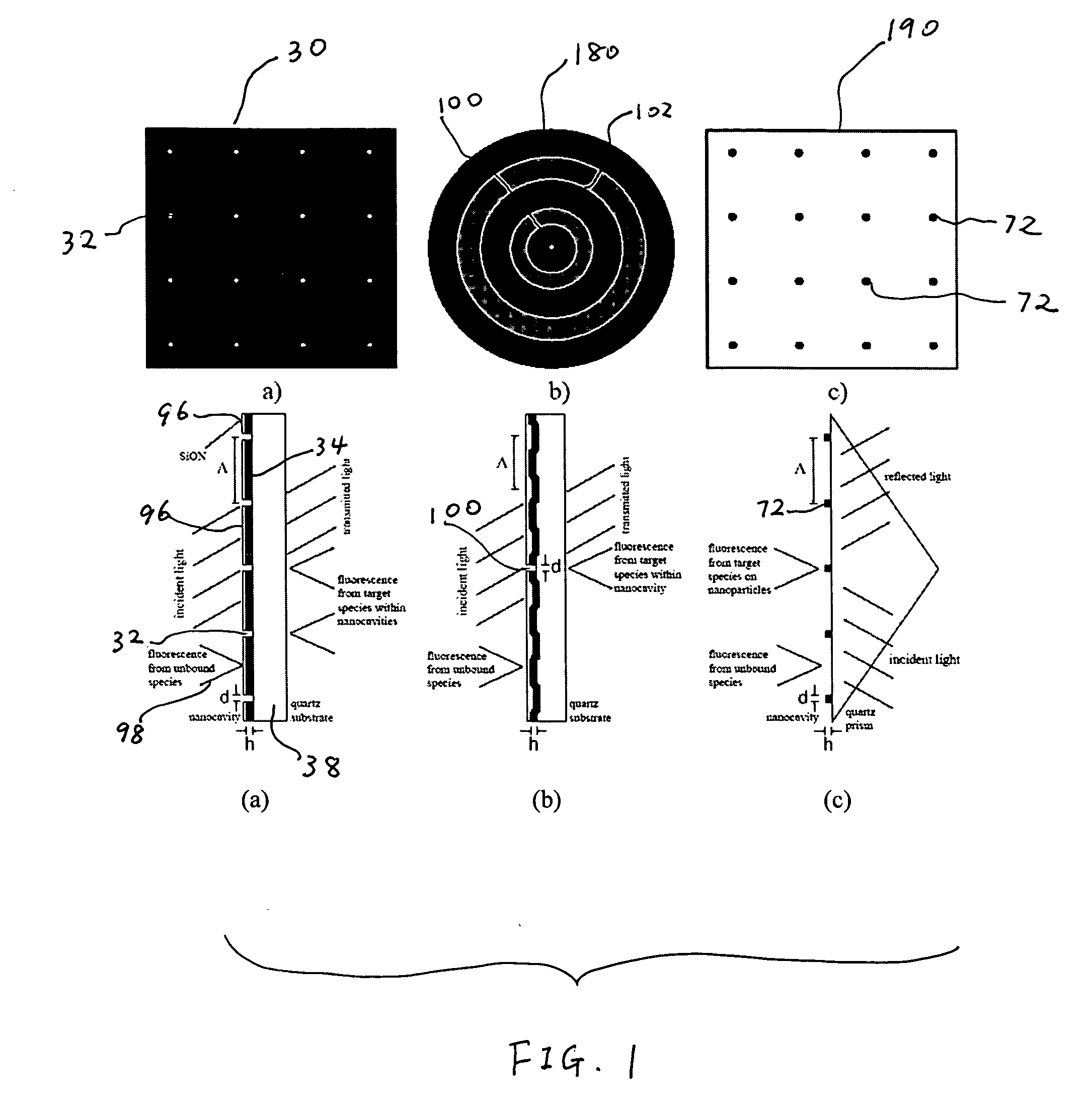
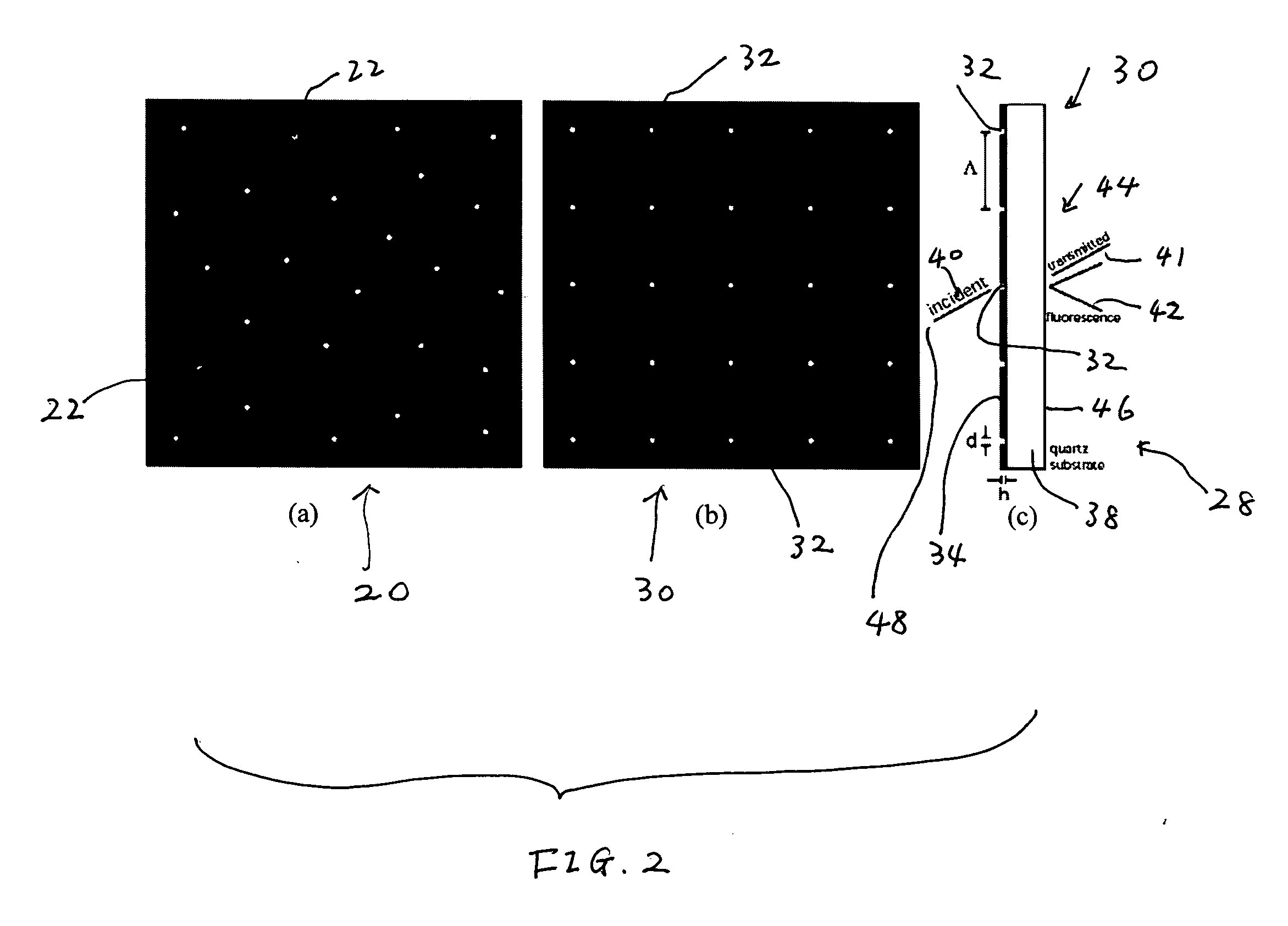
modes can constructively interfere within the nanocavities. For example, when incident light is to be directed from the substrate, or back side of the biomolecular assay, and
fluorescence is to be detected at a location adjacent to the opposite, top surface of the biomolecular assay (i.e., the surface by which the metallic film is carried), the metallic film prevents excitation of fluorophores in the bulk solution, which is located over the
metallic substrate. As another example, when incident light is directed toward the biomolecular assay from a location over the metallic film and detection occurs at a location adjacent to the back side of the substrate, although marker molecules that remain within solution may undergo a change in state (e.g., fluorescence by fluorescent marker molecules), the marker molecules that remain in solution over the metallic film remain substantially undetected. This is because light emitted from a location above the metallic film does not pass through the metallic film and since the size of each nanocavity may be too small for
fluorescent light emitted from locations over the surface of the metallic film to pass therethrough.
Fluorescent light generated within the nanocavities does exit the nanocavities, however, and is enhanced by the materials from which the nanocavities are formed, as well as by the configurations and dimensions of the nanocavities.
[0017]The shapes of the nanocavities may be configured to optimize
signal amplification. It has been discovered that nanocavities of a variety of shapes, including circular, square, and triangular, provide a good degree of radiative, or signal, enhancement, depending upon the dimensions (e.g., diameters of circular nanocavities, edge lengths of square and triangular nanocavities, etc.) of the nanocavities. Square nanocavities may provide better
signal enhancement than circular nanocavities, while triangular nanocavities may provide even greater
signal enhancement. Without limiting the scope of the invention, circular nanocavities formed in a
gold film having a thickness of about 100 nm may enhance a signal by up to about 1.8 times (for nanocavities having diameters of about 160 nm), square nanocavities formed in a
gold film having a thickness of about 100 nm may enhance a signal by up to about 2.1 or 2.2 times (for nanocavities with edges of about 125 nm in length and 20 nm
radius corners), and equilateral triangular cavities formed in a
gold film having a thickness of about 100 nm may enhance a signal by up to about 3 times (for nanocavities with edges that are about 175 nm long an that have 20 nm
radius corners). It is believed that even greater radiative, or signal, enhancements may be achieved by further tailoring the shapes or dimensions of nanocavities.
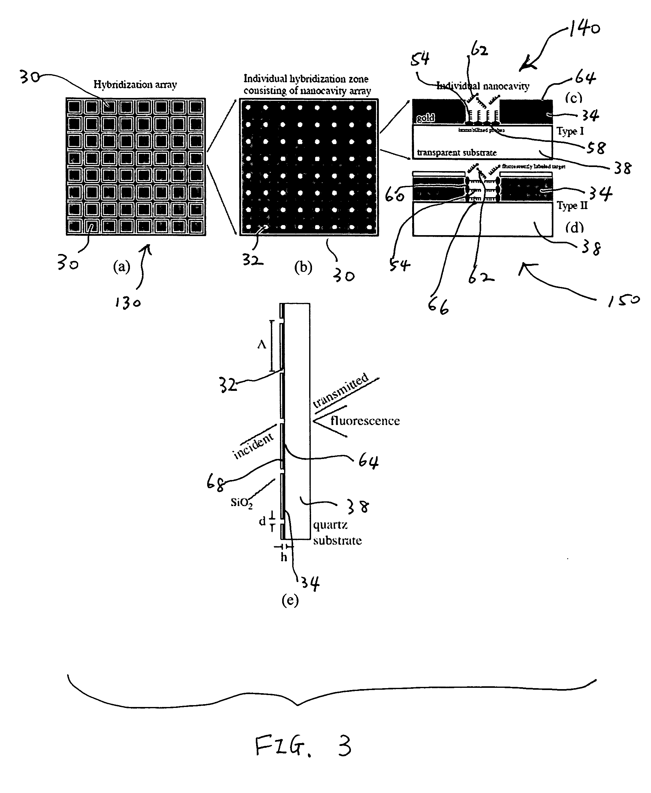
[0019]Surfaces of the biomolecular substrate may be passivated to prevent capture molecules (e.g., bait molecules) from adhering, or being immobilized, to undesired locations thereof. The surfaces of the metallic film may be passivated, for example, with
polyethylene glycol (PEG)-
thiol, another
metal (e.g., gold)-selective
thiol molecule, or any other material that prevents capture molecules from being immobilized to the metallic film, or reduce immobilization of capture molecules to the metallic film. Thus, the capture molecules are instead immobilized to the surface of the substrate exposed to and located within or adjacent to the nanocavities. Alternatively, the exposed surfaces of the substrate may be passivated (e.g., with PEG
silane) to prevent capture molecules from adhering to the substrate and, rather, causing the capture molecules to be immobilized only to the metallic surfaces. As another alternative, a major surface of the metallic film may be covered with a
coating film (e.g., another transparent film), and the exposed surfaces of the
coating film, as well as surfaces of the substrate that are exposed through the
coating film and the metallic film, may be passivated, causing capture molecules to adhere only to the unpassivated exposed edges of the metallic film, which form part of the surface of each nanocavity.
[0020]The biomolecular substrate may be configured in such a way that surface modes (e.g., surface plasmons, which generate an evanescent field) may be generated at the surface of the metallic film or at the portions of the surface of the substrate that are exposed by the nanocavities. These surface modes may provide enhanced excitation of marker molecules on
analyte that has been bound to capture molecules within the nanocavities, particularly surface modes that constructively interfere with one another.
[0026]Once a sample has traveled through the
delivery system, it may be recycled through the
system one or more times. Recycling may be effected in a loop, in which the sample travels through the
system in the same direction each time, or may be effected by reversing the direction in which the sample flows through the
delivery system. Recycling may be useful for optimizing detection of low
analyte concentrations in a sample or for detecting
analyte in samples having small volumes.
[0029]The use of a sequential
delivery system, sample recirculation, sample flow facilitation, sample mixing, or any combination thereof may reduce the amount of
reagent required for detecting an analyte in a sample.



