Single phase liquid refrigerant cryoablation system with multitubular distal section and related method

a liquid refrigerant and single-phase technology, applied in the field of single-phase liquid refrigerant cryoablation system with multi-tubular distal section, can solve the problems of nitrous oxide cooling system not being able to achieve temperature and cooling power, cryosurgical applications are strictly limited, and the effect of “vapor lock”

Inactive Publication Date: 2010-10-07
CRYOMEDIX
View PDF58 Cites 55 Cited by
  • Summary
  • Abstract
  • Description
  • Claims
  • Application Information

AI Technical Summary

Benefits of technology

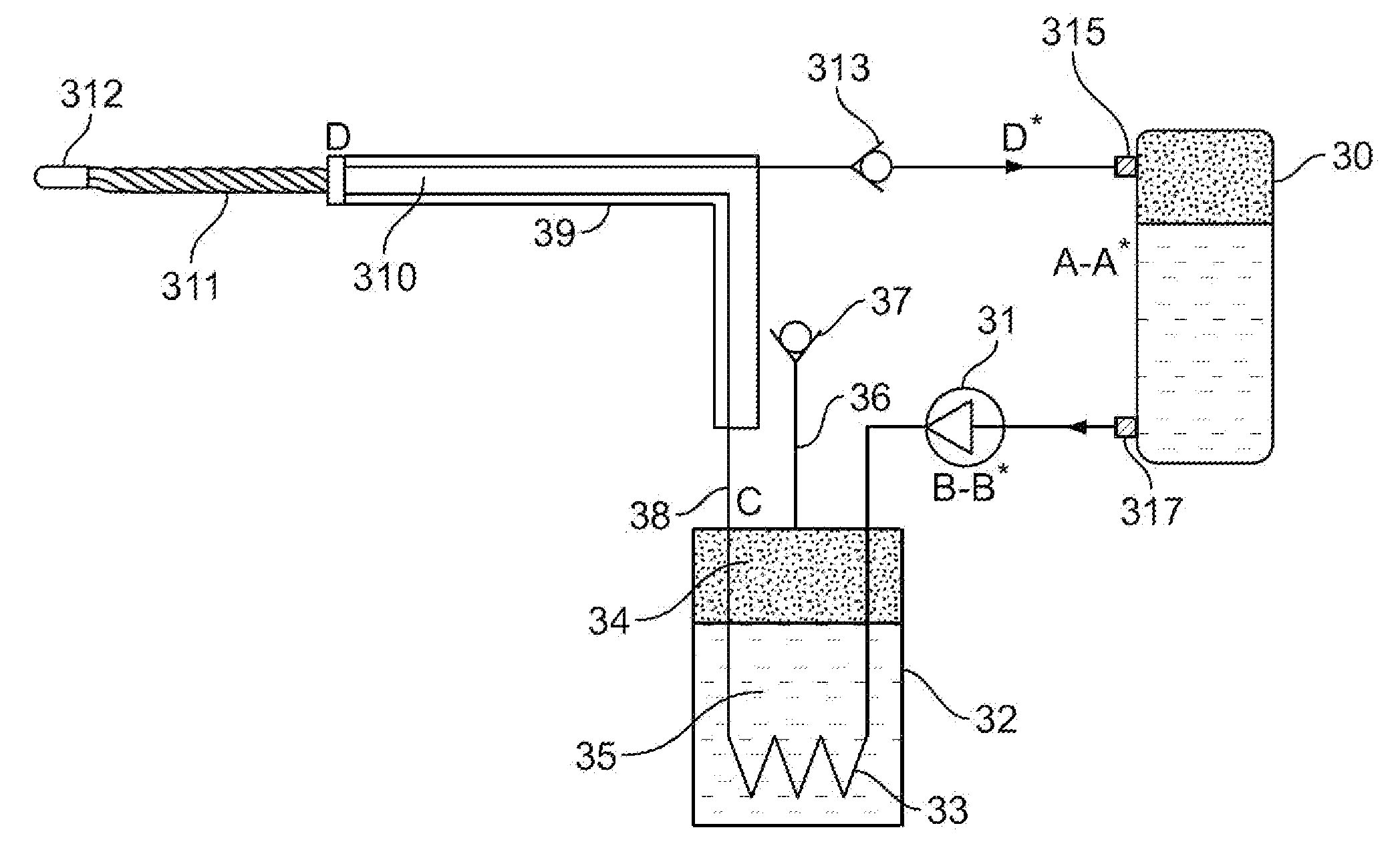
[0012]In one embodiment, the return microtubes are fluidly coupled to at least one cryogen return line which transports the liquid refrigerant to the container thereby completing a circulation flow path of the liquid refrigerant without the liquid refrigerant evaporating. A check valve or another pressure reducer can be positioned along the flowpath between the return line and the container to reduce the pressure of the liquid refrigerant prior to entering the container.
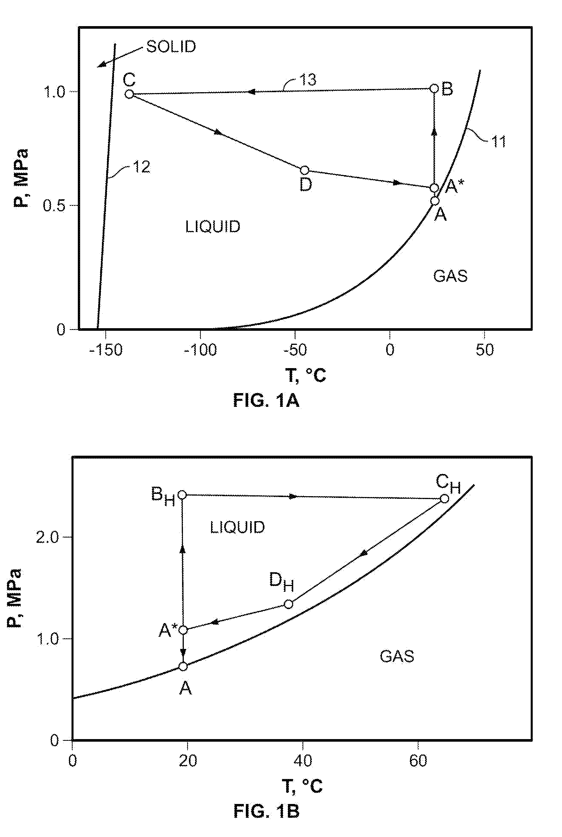
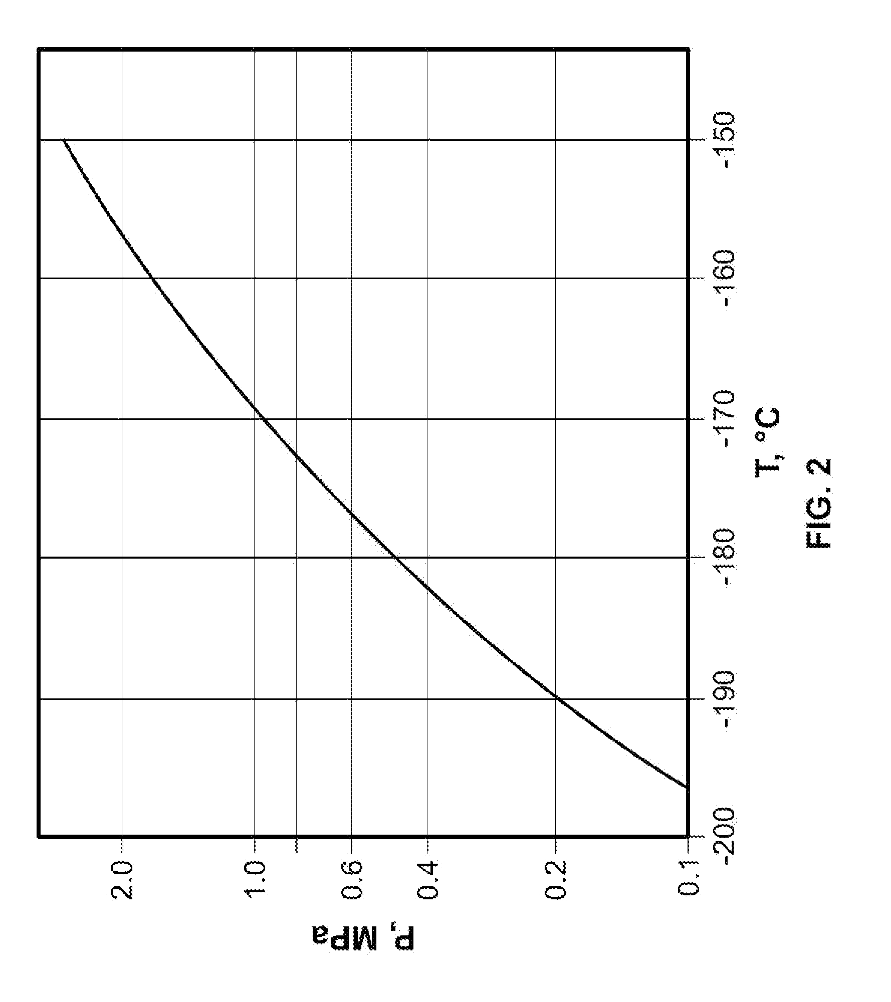
[0017]In another embodiment the system operates at relatively low pressure. The initial pressure is between 0.4 to 0.9 MPa and the compressed pressure along the flowpath after compression is between 0.6 to 1.0 MPa. This has an advantage of allowing operation with a small liquid pump.
[0019]In another embodiment, the bundles of microtubes are sufficient to increase the surface area of cooling surfaces, and therefore increase the heat transfer (cooling) to the target tissue. The number of microtubes is in a range of 5 to 100 microtubes. The plurality of cooling microtubes may be positioned circumferentially about the bundle of return microtubes forming an annulus configuration.
[0022]In another embodiment, a cryoablation method for applying cryoenergy to tissue includes moving a liquid refrigerant along an enclosed flowpath without the liquid refrigerant changing states. The method further includes positioning a distal section of the cryoprobe in the vicinity of the target tissue and transferring cryoenergy to the tissue through the walls of a plurality of cooling microtubes which extend along the distal section of the cryoprobe. The plurality of microtubes may be flexed such that the distal section conforms to the tissue targeted for ablation to increase transfer of energy to the tissue.

Problems solved by technology

This enormous increase in volume results in a “vapor lock” effect when the internal space of the mini-needle of the cryoprobe gets “clogged” by the gaseous nitrogen.
Additionally, in these systems the gaseous nitrogen is simply rejected directly to the atmosphere during use which produces a cloud of condensate upon exposure to the atmospheric moisture in the operating room and requires frequent refilling or replacement of the liquid nitrogen storage tank.
The nitrous oxide cooling system is not able to achieve the temperature and cooling power provided by liquid nitrogen systems.
However, because of the insufficiently low operating temperature, combined with relatively high initial pressure, cryosurgical applications are strictly limited.
These heat exchanger systems are not compatible with the desired miniature size of probe tips that need to be less than 3 mm in diameter.
Although an argon system is capable of achieving a desirable cryoablation temperature, argon systems do not provide sufficient cooling power and require very high gas pressures.
These limitations are very undesirable.
However, challenges arise from use of a near-critical cryogen in a cryoablation system.
In particular, there is still a significant density change in nitrogen once it is crossing its critical point (about 8 times)—resulting in the need for long pre-cooling times of the instrument.
The heat capacity is high only close to the critical point and the system is very inefficient at higher temperatures requiring long pre-cooling times. Additionally, the system does not warm up (or thaw) the cryoprobe efficiently.
Additionally, near-critical cryogen systems require a custom cryogenic pump which is more difficult to create.

Method used


Image

  • Single phase liquid refrigerant cryoablation system with multitubular distal section and related method
  • Single phase liquid refrigerant cryoablation system with multitubular distal section and related method
  • Single phase liquid refrigerant cryoablation system with multitubular distal section and related method

Examples


Embodiment Construction

[0038]Before the present invention is described in detail, it is to be understood that this invention is not limited to particular variations set forth herein as various changes or modifications may be made to the invention described and equivalents may be substituted without departing from the spirit and scope of the invention. As will be apparent to those of skill in the art upon reading this disclosure, each of the individual embodiments described and illustrated herein has discrete components and features which may be readily separated from or combined with the features of any of the other several embodiments without departing from the scope or spirit of the present invention. In addition, many modifications may be made to adapt a particular situation, material, composition of matter, process, process act(s) or step(s) to the objective(s), spirit or scope of the present invention. All such modifications are intended to be within the scope of the claims made herein.

[0039]Methods ...


PUM


Abstract

Single phase liquid refrigerant cryoablation systems and methods are described herein. The cryoablation systems drive liquid cryogen or refrigerant along a closed fluid pathway without evaporation of the liquid cryogen. A cryoprobe includes a distal energy delivery section to transfer energy to the tissue. A plurality of cooling microtubes positioned in a distal section of the cryoprobe transfer cryogenic energy to the tissue. The plurality of microtubes in the distal section are made of materials which exhibit flexibility at cryogenic temperature ranges, enabling the distal section of the cryoprobe to bend and conform to variously shaped target tissues.

Description

CROSS-REFERENCE TO RELATED APPLICATIONS[0001]The present application claims the benefit of application Ser. No. 61 / 167,057, filed Apr. 6, 2009, entitled “Cryogenic System for Improved Cryoablation Treatment”.BACKGROUND OF THE INVENTION[0002]This invention relates to cryoablation systems for treating biological tissues, and more particularly, to cryoablation probes using refrigerants in the liquid state and cryosurgical probes with multitubular distal ends.[0003]Cryosurgical therapy involves application of extremely low temperature and complex cooling systems to suitably freeze the target biological tissues to be treated. Many of these systems use cryoprobes or catheters with a particular shape and size designed to contact a selected portion of the tissue without undesirably affecting any adjacent healthy tissue or organ. Extreme freezing is produced with some types of refrigerants that are introduced through the distal end of the cryoprobe. This part of the cryoprobe must be in dire...

Claims


Application Information

Patent Timeline
Patent Type & Authority Applications(United States)
IPC IPC(8): A61B18/02
CPCA61B18/02A61B2018/0262A61B2018/0212
Inventor BABKIN, ALEXEILITTRUP, PETERNYDAM, WILLIAMNYDAM, BARRON
Owner CRYOMEDIX
Why Eureka
Try Eureka