Film forming method and film forming apparatus for transparent electrically conductive film

a technology of transparent electrically conductive film and forming method, which is applied in the direction of electrolysis components, vacuum evaporation coatings, coatings, etc., can solve the problems of increasing costs, achieve low specific resistance, maintain transparency, and lower the specific resistance of zinc oxide-based transparent electrically conductive films

Inactive Publication Date: 2010-10-14
ULVAC INC
View PDF6 Cites 5 Cited by
  • Summary
  • Abstract
  • Description
  • Claims
  • Application Information

AI Technical Summary

Benefits of technology

[0027]Since the film forming method for a transparent electrically conductive film of the present invention performs sputtering in a reactive gas atmosphere that contains two types or three types that are selected from the group of hydrogen gas, oxygen gas, and water vapor, it is possible to lower the specific resistance of the zinc oxide-based transparent electrically conductive film, and moreover it is possible to maintain the transparency with respect to visible light rays.
[0028]Accordingly, it is possible to readily form a zinc oxide-based transparent electrically conductive film with low specific resistance and excellent transparency with respect to visible light rays.
[0029]Since the film forming apparatus for a transp...

Problems solved by technology

However, indium (In), which is the raw material of ITO, is a rare metal, an...

Method used


Image

  • Film forming method and film forming apparatus for transparent electrically conductive film
  • Film forming method and film forming apparatus for transparent electrically conductive film
  • Film forming method and film forming apparatus for transparent electrically conductive film

Examples


first embodiment

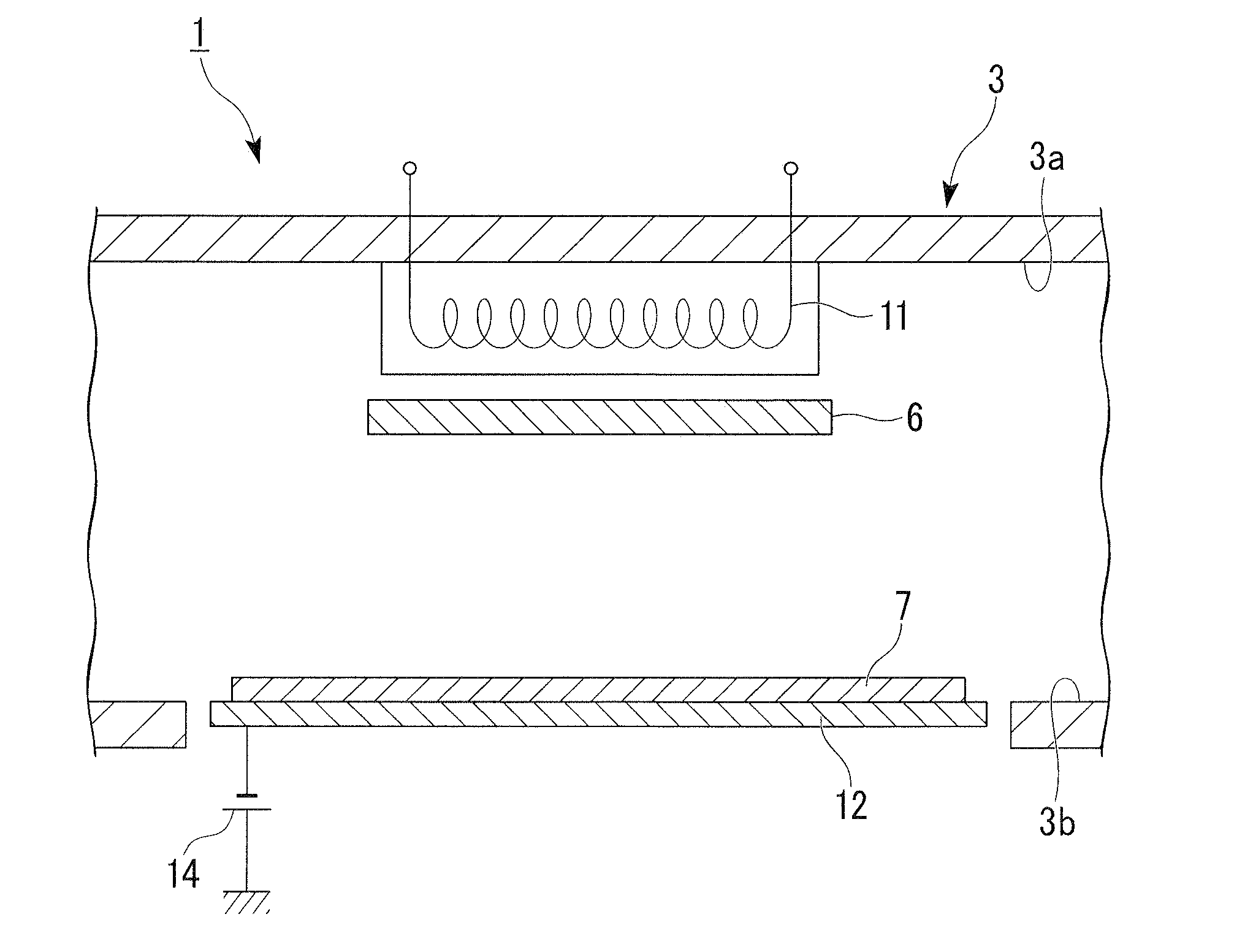
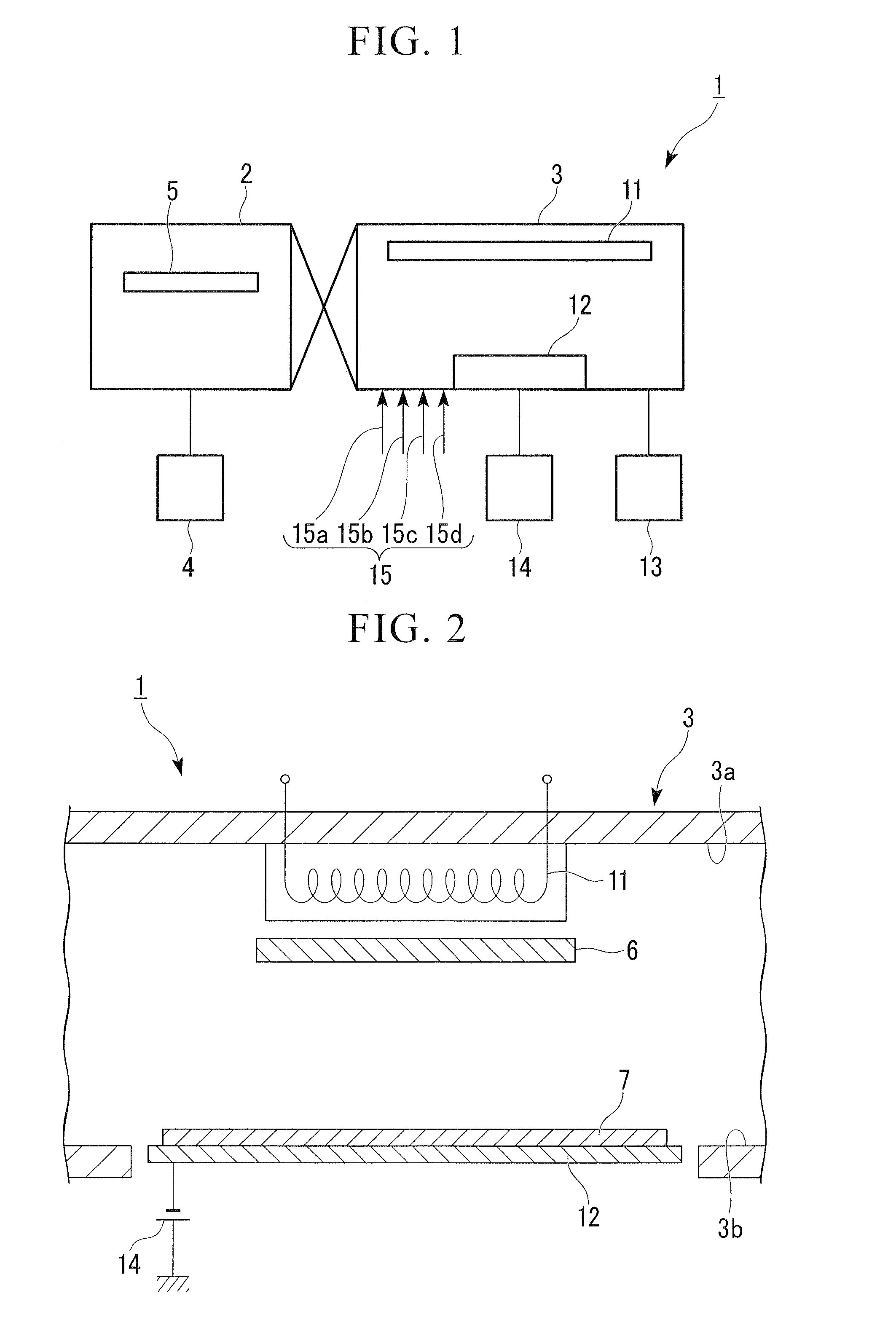
[0068]FIG. 1 is a schematic configuration drawing (plan view) that shows the sputtering apparatus (film forming apparatus) of the first embodiment of the present invention, and FIG. 2 is a plan cross-sectional view that shows the essential portions of the film forming chamber of the same sputtering apparatus.

[0069]This sputtering apparatus 1 is an interback-type sputtering apparatus, and is provided with a preparation / ejection chamber 2 that for example carries in / carries out a substrate such as an alkali-free glass substrate (not illustrated), and a film forming chamber (vacuum container) 3 in which a zinc oxide-based transparent electrically conductive film is formed on the substrate.

[0070]In the preparation / ejection chamber 2 is provided a rough exhaust unit 4 such as a rotary pump or the like that performs rough vacuuming of this chamber. Also, a substrate tray 5 for holding / moving a substrate is disposed in a movable manner in the chamber of the preparation / ejection chamber 2.

[...

second embodiment

[0133]FIG. 8 is a plan cross-sectional view that shows the essential portions of the film forming chamber of an interback-type magnetron sputtering apparatus of the second embodiment of the present invention.

[0134]A magnetron sputtering apparatus 21 differs from the aforementioned sputtering apparatus 1 on the points of holding the target 7 of a zinc oxide-based material on one side surface 3b of the film forming chamber 3, and a longitudinally-installed sputtering cathode mechanism (target holding unit) 22 that generates a desired magnetic field being provided.

[0135]The sputtering cathode mechanism 22 is provided with a back plate 23 that is bonds (fixes) the target 7 with a brazing material or the like, and a magnetic circuit (magnetic field generating unit) 24 that is disposed along the rear surface of the back plate 23. This magnetic circuit 24 generates a horizontal magnetic field on the front surface of the target 7. The magnetic circuit 24 is provided a plurality of magnetic ...


PUM

PropertyMeasurementUnit
Electric potential / voltageaaaaaaaaaa
Electrical conductivityaaaaaaaaaa
Magnetic fieldaaaaaaaaaa

Abstract

A film forming method for a transparent electrically conductive film that forms a zinc oxide-based transparent electrically conductive film on a substrate by sputtering using a target containing a zinc oxide-based material, performing the sputtering in a reactive gas atmosphere that contains two types or three types selected from among a group consisting of hydrogen gas, oxygen gas and water vapor.

Description

TECHNICAL FIELD[0001]The present invention relates to a film forming method and a film forming apparatus for a transparent electrically conductive film. More specifically, it relates to a preferred film forming method and a film forming apparatus used in various devices in the optoelectronics field, such as a flat panel display (FPD), touch panel, photovoltaic cell, electromagnetic shield, antireflection (AR), membrane, light emitting diode (LED).[0002]Priority is claimed on Japanese Patent Application No. 2007-340913, filed Dec. 28, 2007, the content of which is incorporated herein by reference.BACKGROUND ART[0003]Conventionally, as an electrode material in a photovoltaic cell or light emitting diode, there has been indium tin oxide (ITO) in which tin oxide is added to indium oxide in an amount of 5 to 10 percent by weight, and it is utilized as a transparent electrically conductive material.[0004]However, indium (In), which is the raw material of ITO, is a rare metal, and it is ex...

Claims


Application Information

Patent Timeline
IPC IPC(8): C23C14/08C23C14/34C23C14/35H01B13/00
CPCC23C14/086C23C14/0036
Inventor TAKAHASHI, HIROHISAISHIBASHI, SATORU
Owner ULVAC INC
Why Eureka
Try Eureka