Plasma Processing Apparatus and Plasma Processing Method

a plasma processing and plasma technology, applied in the direction of plasma technique, chemical vapor deposition coating, coating, etc., can solve the problems of affecting the stability of the plasma processing apparatus, so as to improve the stability of the plasma processing performance and the apc

Inactive Publication Date: 2010-10-14
HITACHI HIGH-TECH CORP
View PDF0 Cites 44 Cited by
  • Summary
  • Abstract
  • Description
  • Claims
  • Application Information

AI Technical Summary

Benefits of technology

[0012]The object of the present invention is to provide a plasma processing apparatus capable of detecting the conditions of the apparatus such as the density and distribution of plasma and the consumption of components, which are physical parameters of controlling the plasma processing performance. In addition, the present invention aims at providing a plasma processing method capable of realizing the improvement of stability of the plasma processing performance and the APC for directly controlling the physical parameters, realizing preventive maintenance of the components and the apparatus, and realizing failure diagnosis.

Problems solved by technology

In the etching process, the main cause that variesetching performance is the changes of condition with time of the inner wall surface of the chamber.
However, through conventional monitoring (such as the plasma emission, the RF bias Vpp of the apparatus control parameter or the matching point of source power), it was difficult to distinguish whether the variation appearing on the monitor was caused by the changes of plasma density or by the changes of neutral radicals.
Furthermore, the consumption of the components in the apparatus and the degradation of the insulation coating also causes the plasma density and the neutral radical composition to vary, but since the level of consumption of components and the replacement timings thereof were conventionally determined based on the prescribed discharge time, when the level of consumption of a component exceeded the predicted level, particles were generated and failure occurred, by which the yield was deteriorated.
The plasma density measurement adopting the high frequency antenna probe method disclosed in patent document 2 is advantageous regarding metal contamination and stability, but considering the principle that the surface waves existing between the high frequency antenna and the dielectric body resonate with the plasma close to the probe, the method is only capable of obtaining the plasma density close to the probe and not the data regarding the density within the plasma.

Method used


Image

  • Plasma Processing Apparatus and Plasma Processing Method
  • Plasma Processing Apparatus and Plasma Processing Method
  • Plasma Processing Apparatus and Plasma Processing Method

Examples


embodiment 1

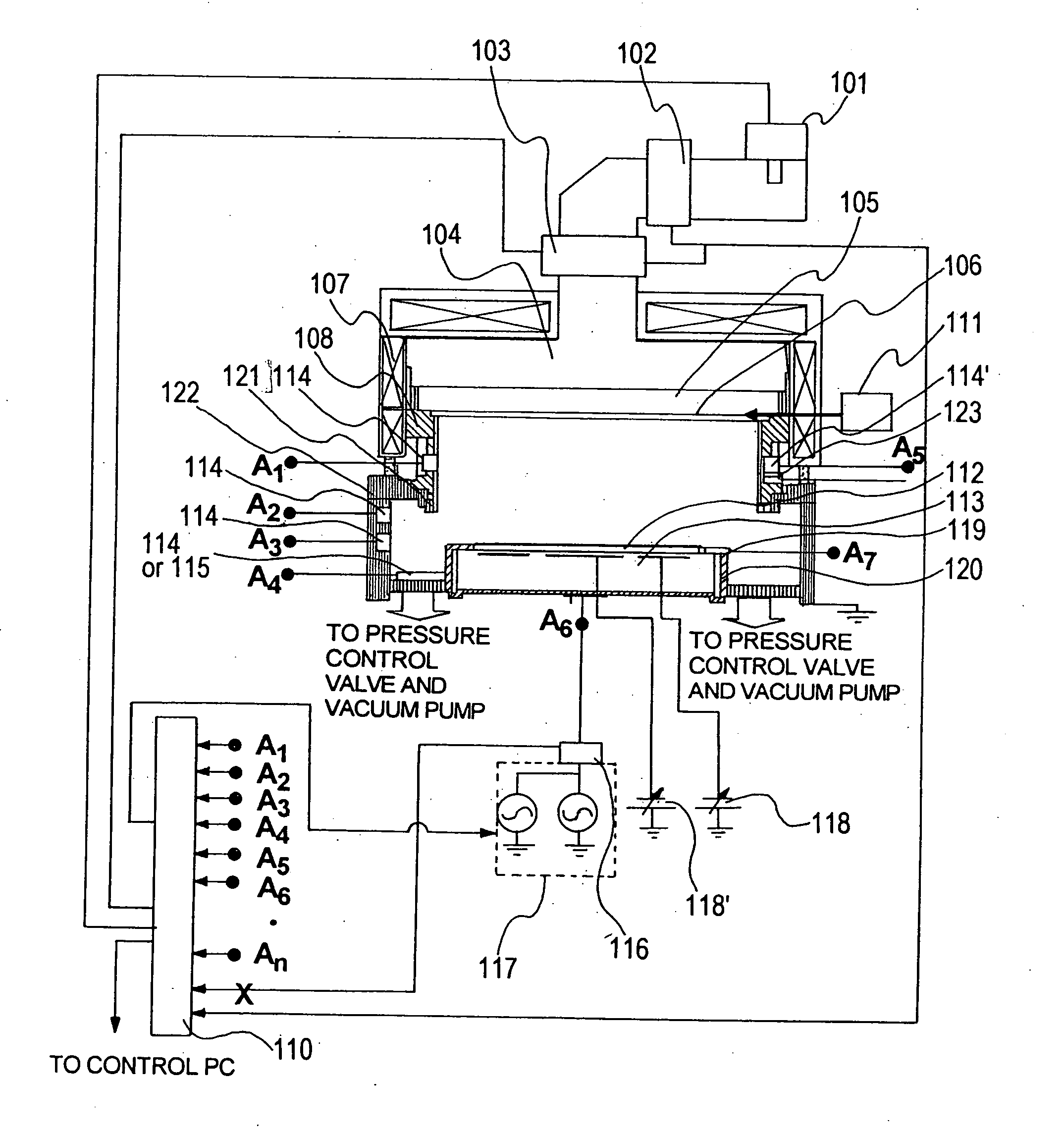
[0034]First, an embodiment of an apparatus for realizing the present invention will be described. FIG. 1 is a vertical cross-sectional view showing an outline of the structure of a plasma processing apparatus according to a preferred embodiment of the present invention. The plasma processing apparatus shown in FIG. 1 is a plasma processing apparatus for generating plasma within a plasma processing chamber arranged in the interior of a vacuum reactor, and for processing a substrate-like sample such as a semiconductor wafer as object to be etched disposed within the plasma processing chamber using the generated plasma.

[0035]The vacuum reactor of the plasma processing apparatus comprises an etching chamber 108 as plasma processing chamber, a quartz plate 105, a shower plate 106, a gas supply means 111, a base frame 122, a vacuum pump and a pressure control valve (both of which are not shown in FIG. 1).

[0036]Means for generating plasma includes a source power supply 101 for generating m...

embodiment 2

[0062]In addition to the example described above where the frequency of the RF bias power supply connected to the lower electrode is utilized as a high frequency oscillator, a method for detecting the conditions of the plasma and the apparatus by connecting a third probe power supply will now be described. FIG. 7 shows an embodiment having means for irradiating UHF waves from the surface of a UHF matching box 602 constituting a plasma generating power supply system through an antenna 604 into the plasma chamber, and connecting at least one of the plurality of connecting points A1 through A9 to point A, thereby measuring the reflection coefficient, the transmission coefficient and the impedance.

[0063]Embodiment 2 differs from embodiment 1 illustrated in FIG. 1 in that the present embodiment comprises a 450-MHz UHF power supply 601 as plasma source power supply constituting a plasma generating means, a UHF matching box 602 and an antenna 604. The antenna 604 for irradiating UHF waves ...

embodiment 3

[0078]FIG. 11 is referred to in illustrating another embodiment where the forms of connection of the probe high frequency oscillation means and the high frequency analysis means differ from FIG. 7. The plasma processing apparatus according to the present embodiment differs from the plasma processing apparatus illustrated in FIG. 7 in that the probe high frequency oscillation means 603 is connected via a directional coupler 605 to a connecting point B1 (A6 in FIG. 7) of the RF bias matching box 116 and the lower electrode 113.

[0079]In other words, the present embodiment is an example where the probe high frequency oscillation means 603 is connected to an RF power supply line of the lower electrode 113. In this example, the thickness direction density can be detected by connecting the signals from receiver A10 and receiver A11 to the high frequency analysis means 110. Further, the average density of plasma intersecting the radial direction of the chamber and the change in the distribu...


PUM

PropertyMeasurementUnit
frequencyaaaaaaaaaa
frequencyaaaaaaaaaa
plasma frequencyaaaaaaaaaa

Abstract

The invention provides a plasma processing apparatus comprising a means for detecting the apparatus condition related to the ion flux quantity of plasma (plasma density) and the distribution thereof for to stabilizing mass production and minimizing apparatus differences. The plasma processing apparatus comprises a vacuum reactor 108, a gas supply means 111, a pressure control means, a plasma source power supply 101, a lower electrode 113 on which an object to be processes 112 is placed within the vacuum reactor, and a high frequency bias power supply 117, further comprising a probe high frequency oscillation means 103 for supplying an oscillation frequency that differs from the plasma source power supply 101 and the high frequency bias power supply 117 into the plasma processing chamber, high frequency receivers 114 through 116 for receiving the high frequency supplied from the probe high frequency oscillation means 603 via a surface coming into contact with plasma, and a high frequency analysis means 110 for measuring the impedance per oscillation frequency within an electric circuit formed by the probe high frequency oscillation means 603 and the receivers 114 through 116, the reflectance and the transmittance, and the variation of harmonic components.

Description

[0001]The present application is based on and claims priority of Japanese patent application No. 2008-173762 filed on Jul. 2, 2008, the entire contents of which are hereby incorporated by reference.BACKGROUND OF THE INVENTION[0002]1. Field of the Invention[0003]The present invention relates to a plasma processing apparatus and a plasma processing method used for performing dry etching and CVD in the process for manufacturing semiconductor devices and flat panel displays (FPD).[0004]2. Description of the Related Art[0005]Etching devices are required to have a high operating rate and a high yield in a dry etching step, which is one of the steps for manufacturing semiconductor devices and FPD. In order to improve the operating rate, clustering of the apparatus is promoted in which a single apparatus is equipped with a plurality of chambers, and in that case, the differences in performances among chambers (inter-chamber difference) or among apparatuses (inter-apparatus difference) must ...

Claims


Application Information

Patent Timeline
Patent Type & Authority Applications(United States)
IPC IPC(8): H01L21/306H01L21/02C23C16/513
CPCH01J37/32091H01J37/32155H01J37/3299H01J37/32192H01J37/32935H01J37/32165H01L21/3065
Inventor MORI, MASAHITOTETSUKA, TSUTOMUITABASHI, NAOSHI
Owner HITACHI HIGH-TECH CORP
Why Eureka
Try Eureka