
Electrode for electric double layer capacitor and method for producing the same

Active Publication Date: 2010-10-14
NIPPON CHIMI CON CORP
View PDF5 Cites 15 Cited by
  • Summary
  • Abstract
  • Description
  • Claims
  • Application Information

AI Technical Summary

Benefits of technology

[0010]It is an object of the present invention, which is proposed in order to resolve the aforementioned problems of prior art, to provide an electrical double layer capacitor electrode with excellent capacitance characteristics that can be manufactured by simple operations in comparison with the invention of Patent Document 2, along with a manufacturing method therefor.
[0016]In one mode of the present invention, a small amount of a resin or other binder or a conductive auxiliary material or the like can be used to prevent dissipation of the carbon nanotubes when the carbon nanotubes are paper molded. Even in this case the capacitance characteristics can still be greatly improved to the extent that the amount of binder is much less than the amount required when using a binder to integrate carbon nanotubes with a collector.
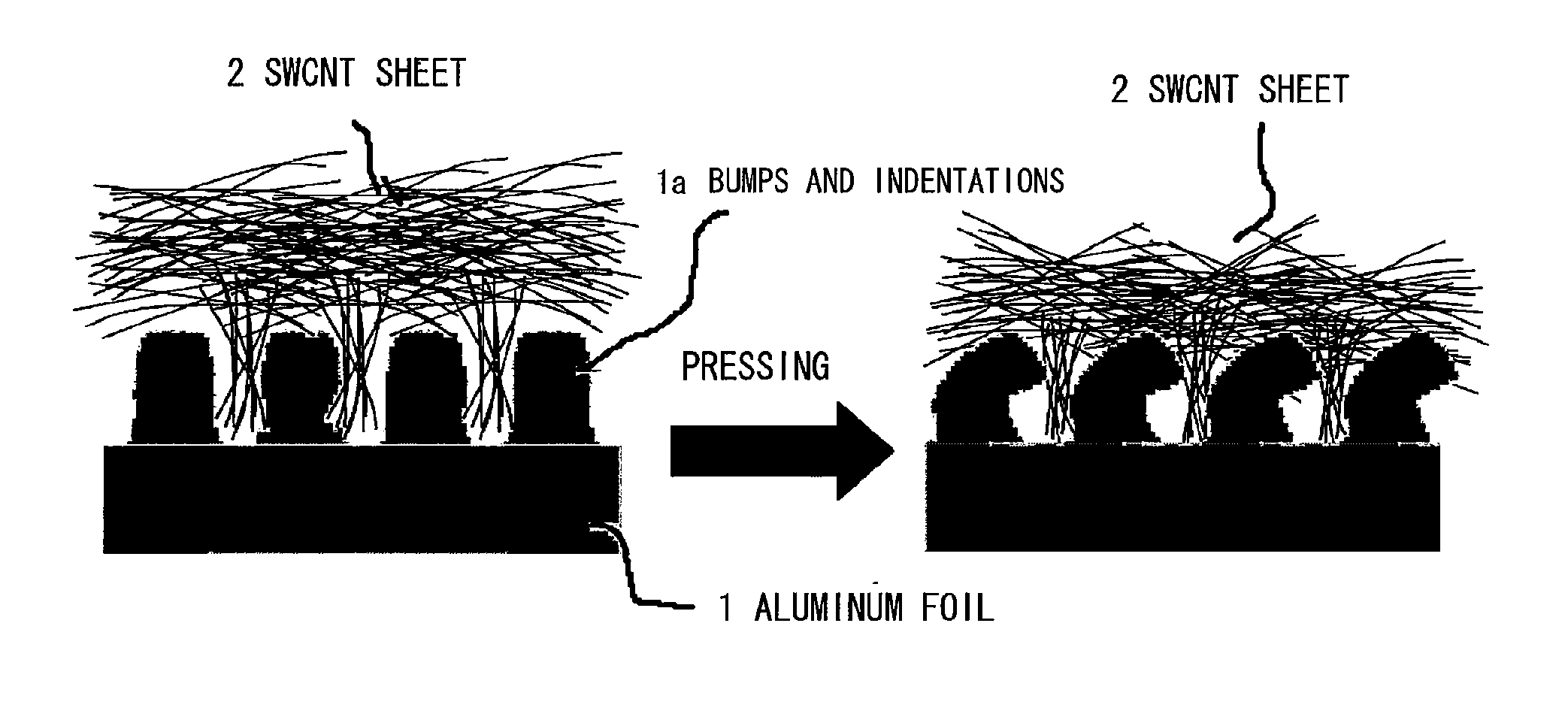
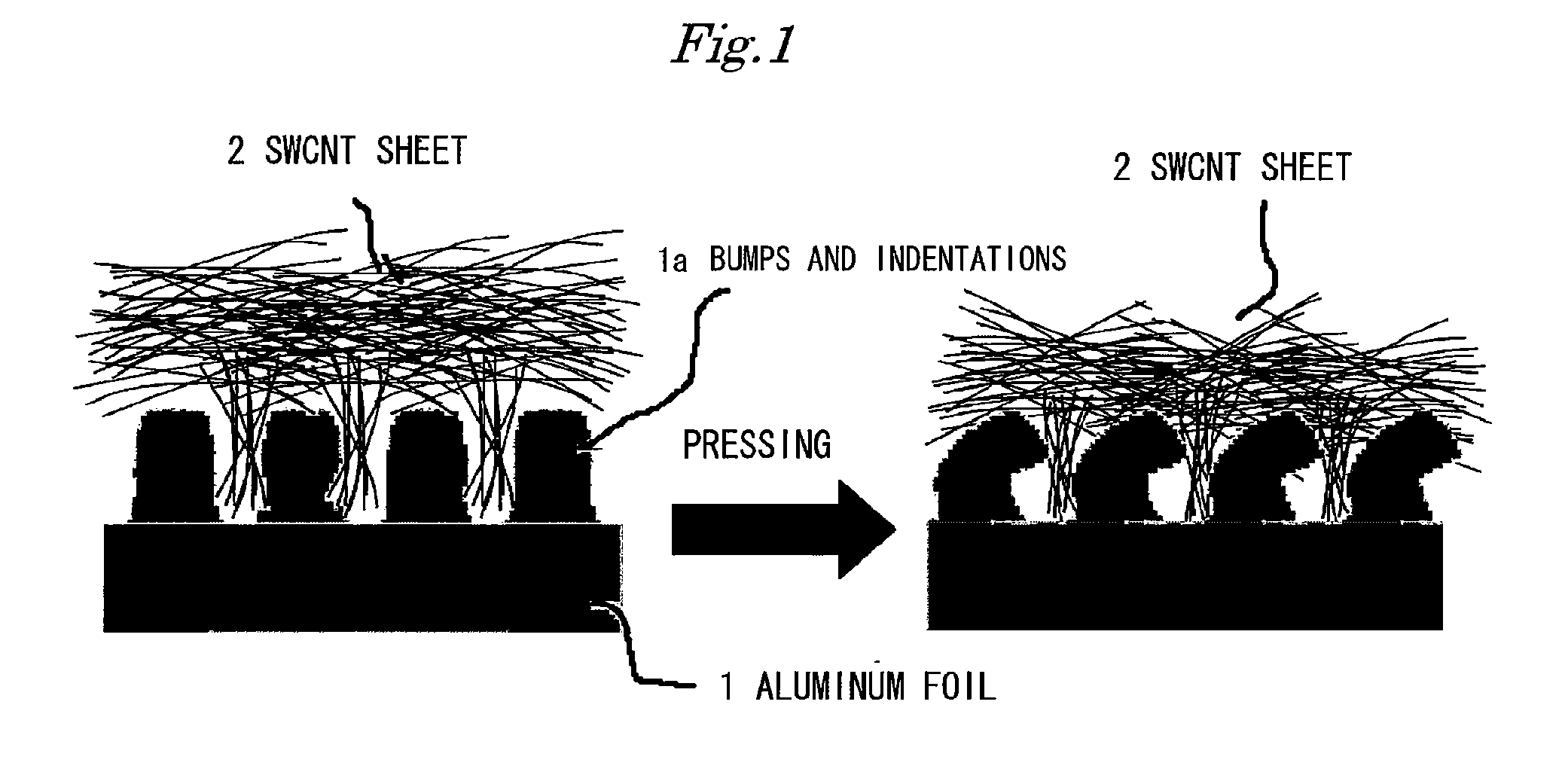
[0018]With the present invention having the configuration described above, because the carbon nanotubes and etched foil of the collector are integrated with the bumps and indentations of the etched foil worked into the carbon nanotubes, the conductive material contacts the collector directly without the need for a resin or other binder or conductive auxiliary or other material, thereby reducing electrical resistance and providing an electrical double layer capacitor electrode with excellent capacitance characteristics.
[0019]This applies not only to etched foils but also when the collector is a substrate having bumps and indentations on the surface, especially a nickel foam or other porous metal body, and if a porous metal body is used in particular the apparent density is reduced by the hollows inside the metal body, resulting in a lighter collector and making it possible to obtain an electrical double layer capacitor electrode with excellent capacitance characteristics. Using nickel foam in particular, it is possible to obtain an electrical double layer capacitor electrode with excellent capacitance characteristics and having an apparent density of 0.2 g / cc (porosity 98%) which is lighter than that of an etched foil (about 1.0 g / cc minimum in the case of an Al etched foil).
[0020]An electrical double layer capacitor electrode with even better electrical characteristics can be obtained by using for the paper molded sheet of carbon nanotubes a carbon nanotube aggregate with a density of 0.5 to 1.5 g / cm3 obtained by using ultrahigh-pressure treatment to break up bundles and macro-aggregations of CNTs and so that the CNTs are deposited with high dispersion.

Problems solved by technology

However, double layer capacity provides lower energy densities than batteries, making it inadequate as a power source for electrical automobiles, so there is a need for further improvements in storage capacity density.
However, the problem with the invention described in Patent Document 1 above is that an electrode with good capacitance characteristics cannot be obtained because a resin component is used for the binder.

Method used


Image

  • Electrode for electric double layer capacitor and method for producing the same
  • Electrode for electric double layer capacitor and method for producing the same
  • Electrode for electric double layer capacitor and method for producing the same

Examples


example 1

[0055]About 50 mg of single-walled carbon nanotubes (SWCNTs) were measured, mixed with 50 ml of methanol, and agitated for about 30 seconds in an ordinary mixer to obtain a dispersion of SWCNT and methanol. This dispersion was filtered under reduced pressure with PTFE filter paper (di. 35 mm, average pore size 0.2 μm) to obtain paper molded SWCNT sheets. These were cut to the same size as the collectors, laid over etched aluminum foil, unetched aluminum foil, copper foil and platinum foil collectors, sandwiched with aluminum foil, and pressed for 1 minute under 10 t / cm2 of pressure from above and below the foils.

example 2

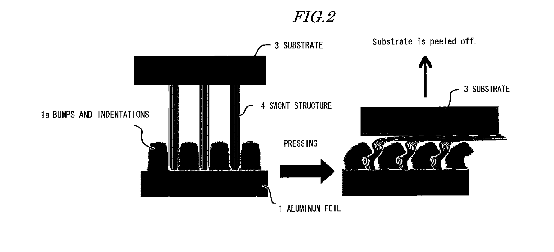
[0056]Etched aluminum foil, unetched aluminum foil, copper foil and platinum foil were laid separately as collectors the same size as the substrate over SWCNT structures grown on substrates by CVD, and pressed with high pressure under the same conditions as in Example 1. After pressing, the sandwiched aluminum foils were removed, and the collectors affixed to the substrates by pressing were peeled off to transfer the SWCNT structures to the surfaces of the collectors.

example 3

[0063]Pressing was performed as in Example 1 using a SWCNT sheet paper molded by the same methods as in Example 1 and a collector made of nickel foam, which is a porous metal body with a porosity of 98% and a density of 0.18 g / cm3 (Sumitomo Electric Industries Celmet (trademark) in this example).


PUM

PropertyMeasurementUnit
Densityaaaaaaaaaa
Pressureaaaaaaaaaa
Capacitanceaaaaaaaaaa

Abstract

An electrical double-layer capacitor electrode with excellent capacitance characteristics is obtained together with a manufacturing method therefor.Paper-molded sheet 2 of carbon nanotubes is integrated with etched foil 1 constituting a collector, by means of bumps and indentations 1a formed on the surface of etched foil 1 to prepare an electrical double-layer capacitor electrode. Alternatively, carbon nanotubes 4 grown around core catalyst particles on substrate 3 are integrated with etched foil 1 by means of bumps and indentations 1a formed on the surface of etched foil 1 to prepare an electrical double-layer capacitor electrode. To manufacture these electrodes, this carbon nanotube sheet 2 or substrate 3 with carbon nanotubes grown thereon is laid over bumps and indentations la on the surface of etched foil 1, and the sheet or substrate and the foil are pressed under 0.01 to 100 t / cm2 of pressure to integrate the carbon nanotubes with the etched foil.

Description

TECHNICAL FIELD[0001]The present invention relates to an electrical double layer capacitor electrode that has been improved so as to provide excellent capacitance characteristics, and to a manufacturing method therefor.BACKGROUND ART[0002]An electrical double layer capacitor has active carbon or other polarizable electrodes as the positive and negative electrodes, and an electrolyte solution consisting of a quaternary onium salt of boron tetrafluoride or phosphorus hexafluoride dissolved in an organic solvent such as propylene carbonate. In such an electrical double layer capacitor, the electrostatic capacity is the electrical double layer at the boundary between the electrode surface and the electrolyte solution, with the advantage that since there is no reaction involving ions as in a battery, the charge-discharge characteristics are good, and there is little capacity deterioration attributable to the charge-discharge cycle.[0003]Consequently, electrical double layer capacitors ar...

Claims


Application Information

Patent Timeline
IPC IPC(8): H01G9/058B32B37/10B32B38/00B32B38/10H01G11/28H01G11/36H01G11/70
CPCH01G9/016H01G9/058H01G9/155Y10T29/417H01G11/36H01G11/70Y02E60/13H01G11/28H01G11/86H01G11/22H01G11/74
Inventor MACHIDA, KENJISUEMATSU, SHUNZOTAMAMITSU, KENJI
Owner NIPPON CHIMI CON CORP
Learn More