Chemical mechanical fabrication (CMF) for forming tilted surface features

a technology of mechanical fabrication and tilting surface, which is applied in the direction of manufacturing tools, lapping machines, transportation and packaging, etc., can solve the problems of not being able to develop tilted surfaces, not being able to generally use them for forming tilted surface features, and affecting the polishing rate of the surface, so as to achieve different polishing rates, improve the polishing rate, and improve the effect of polishing ra

Inactive Publication Date: 2010-10-14
UNIV OF FLORIDA RES FOUNDATION INC +1
View PDF9 Cites 20 Cited by
  • Summary
  • Abstract
  • Description
  • Claims
  • Application Information

AI Technical Summary

Benefits of technology

[0007]Embodiments of the invention generally comprise providing a substrate having a patterned surface. The “patterned” surface for CMF processing can be a planar surface, where the “pattern” refers only to different compositions (that have different polishing rates) on different areas of the surface, referred to herein as compositionally patterned. The two or more layers of different compositions provide a polishing selectivity of >1.5, and can provide a polishing selectivity of >20, such as >20 to 100.
[0008]The patterned surface can also be a non-planar surface that comprises at least one pre-CMF protruding or recessed feature. In the protruding or recessed feature embodiment, the protruding or recessed feature comprises a first composition, and has a pre-CMF high elevation portion and a pre-CMF low elevation portion. A vertical distance (height) between the pre-CMF high portion and pre-CMF low portion is ≧10 nm. The pre-CMF high portion includes a center portion and an edge portion. In this embodiment The pre-CMF high portion is contacted with a polishing pad having a slurry composition therebetween. The slurry composition is moved to polish the center and edge portion, wherein the edge portion polishes at a faster polishing rate as compared to a polishing rate of the center portion to form at least one tilted surface feature. The tilted surface feature formed comprises at least one surface portion having a surface

Problems solved by technology

Techniques such as RIE can cause pits and defects e.g. amorphization in the surface thus altering the surface and subsurface microstructure from the bulk.
However, if the surface comprises a single surface compositions (feature material the same as the substrate material), the surface generally remains planar during overpolish and is thus not generally useful for forming tilted surface features.
These techniques are suited to provide vertical-like surface features, with limited ability to develop tilted surfaces.
RIE, mechanical sawing or laser cutting also create significant subsurface damage that can extend at

Method used


Image

  • Chemical mechanical fabrication (CMF) for forming tilted surface features
  • Chemical mechanical fabrication (CMF) for forming tilted surface features
  • Chemical mechanical fabrication (CMF) for forming tilted surface features

Examples


example 1

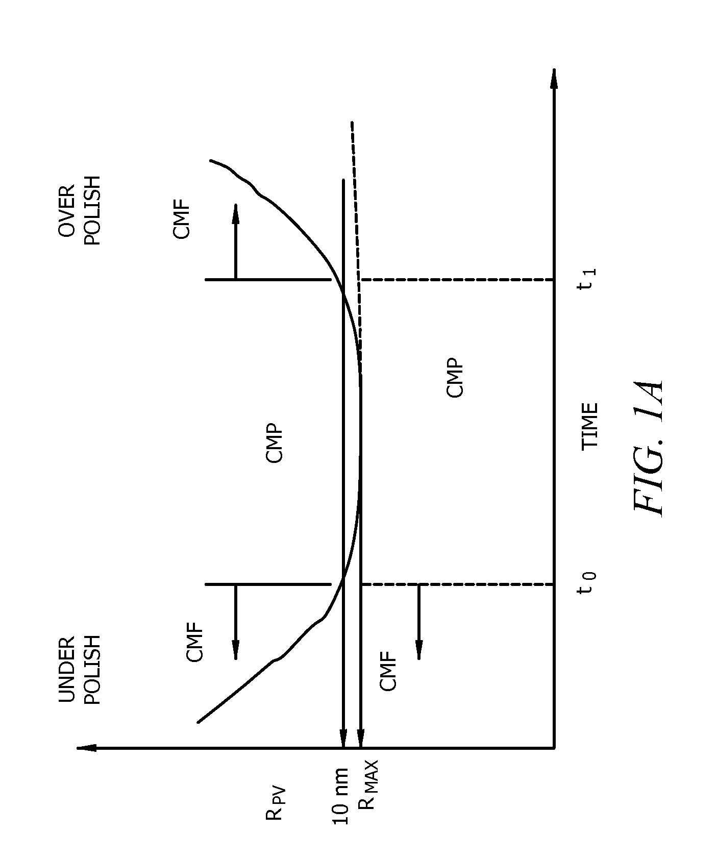
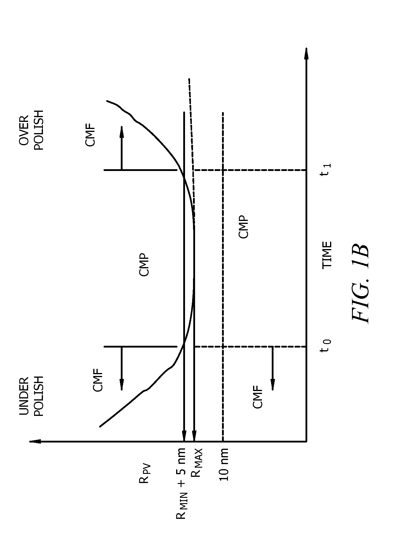
[0072]This Example depicts the formation of microlens-like structures using the CMF method on silica or glass-like surfaces. Flat silica substrates were patterned by RIE to obtain approximately 700 nm tall substantially planar top pillars as shown in the depictions based on AFM images shown in FIG. 9A. The CMP method was then used in the underpolish CMF regime to create microlens structures shown. Using a 5 weight % 80 nm silica slurry, the pillars were polished at pH 4.0 and 2.5 psi using a Struers Rotopol machine. A politex pad was used for this fabrication process. The planarization time for such a structure was determined to be 250 seconds (corresponding to t0 shown in FIGS. 1A and 1B). The depiction based on an AFM image shown in FIG. 9B evidences the formation of microlens structures. The surface roughness of the structures measured was found to be less than 2A. The h / r ratio of the structures varied from 0.07 at the start of the polishing process and decreased to 0.04 after a...

example 2

[0073]This Example depicts positive and negative curvature structures using the CMF method on silica or glass-like surfaces. The flat silica substrates were patterned by RIE to obtain approximately 700 nm tall substantially planar top pillars as described above. The CMP method was used in the underpolish CMF regime to create microlens structures. Using 5% 80 nm silica slurry, the RIE structures were polished at pH 4.0 and 2.5 psi using a Struers Rotopol machine. A Politex pad was used for this fabrication process. The planarization time for such a structure was determined to be 250 seconds (corresponding to t0 shown in FIGS. 1A and 1B). A depiction based on an AFM image is shown in FIG. 10A along with FIG. 10B which is a plot of the height of the surface along the reference line shown in FIG. 10A which evidences the formation of both positive and negative curvature surfaces. The positive curvature surface is formed on protruding surfaces while negative curvature is formed recessed s...

example 3

[0074]This Example depicts the formation of cone-like structures using the CMF method on silica or glass-like surfaces using chemical etching methods. Flat silica substrates were patterned by chemical etching using a selective etch mask to obtain approximately 2,500 nm tall pillars shown in depiction based on an AFM image shownFIG. 11A. A plot of the height of the surface as a function of lateral distance is also provided. The etching conditions used were 5 vol. percent HF for 4 minutes. The CMP method was then used in the underpolish CMF regime to create a microlens structures. The CMF comprised using 5% 80 nm silica slurry with HNO3 to adjust the pH to 4, and the structures were polished at pH 4.0 and 2.5 psi using a Struers Rotopol machine. A Politex pad was used for this fabrication process. The planarization time for such a structure was determined to be approximately 700 seconds (corresponding to t0). The depiction based on an AFM image of the CMF structures are shown in FIG. ...


PUM


Abstract

A method of chemical-mechanical fabrication (CMF) for forming articles having tilted surface features. A substrate is provided having a patterned surface including two different layer compositions or a non-planar surface having at least one protruding or recessed feature, or both. The patterned surface are contacted with a polishing pad having a slurry composition, wherein a portion of surface being polished polishes at a faster polishing rate as compared to another portion to form at least one tilted surface feature. The tilted surface feature has at least one surface portion having a surface tilt angle from 3 to 85 degrees and a surface roughness<3 nm rms. The tilted surface feature includes a post-CMF high elevation portion and a post-CMF low elevation portion that defines a maximum height (h), wherein the tilted surface feature defines a minimum lateral dimension (r), and h/r is ≧0.05.

Description

CROSS REFERENCE TO RELATED APPLICATIONS[0001]This application claims the benefit of Provisional Application Ser. No. 61 / 168,858 entitled “CHEMICAL MECHANICAL FABRICATION(CMF) FOR FORMING NON-PLANAR OR TILTED SURFACE FEATURES”, filed Apr. 13, 2009, which is herein incorporated by reference in its entirety.FIELD OF THE INVENTION[0002]Disclosed embodiments relate to a variant of a chemical mechanical polishing (CMP) process and articles having tilted surface features therefrom.BACKGROUND[0003]In the last couple of decades CMP has grown from a glass polishing technology to a standard integrated circuit (IC) fabrication technique. CMP ensures the miniaturization of ICs by providing an appropriate copper removal technique for forming metal interconnects and also providing flatter wafer surfaces needed for next generation lithographic tools. CMP is used in both front-end and back-end processing, such as in trench isolation, inter-level dielectric (ILD) planarization, local tungsten interco...

Claims


Application Information

Patent Timeline
IPC IPC(8): B32B3/00B32B43/00
CPCB24B37/042H01L31/0236Y10T428/24612H01L31/0543Y02E10/52H01L31/02366H01L21/304
Inventor SINGH, RAJIV K.KUMAR, PURUSHOTTAMSINGH, DEEPIKAARJUNAN, ARUL CHAKKARAVARTHI
Owner UNIV OF FLORIDA RES FOUNDATION INC
Why Eureka
Try Eureka