

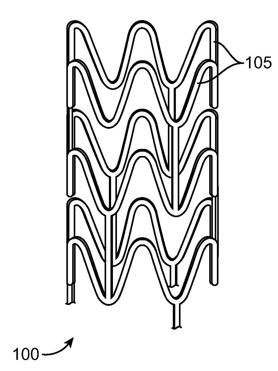
Stent Made From An Ultra High Molecular Weight Bioabsorbable Polymer With High Fatigue And Fracture Resistance
a bioabsorbable polymer and high fatigue resistance technology, applied in the field of stents, can solve the problems of difficult treatment, adverse or even toxic side effects, and the stenosis remains a significant problem, and achieves the effect of improving the resistance and strength of the stent, improving the stent, and improving the sten
- Summary
- Abstract
- Description
- Claims
- Application Information
AI Technical Summary
Problems solved by technology
Method used
Image

Examples
example 1
Exemplary UHMW Resin for Use in Making Stent
[0097]A UHMW polylactide resin with brand name PURASORB PL and batch no. 0404002128 was obtained from PURAC located in the Netherlands. The properties of the resin are:
Appearance:white to light tan granulesInherent Viscosity:8.36 dl / g (chloroform, 25° C.,c = 0.1 g / dl)Specific rotation (chloroform 25° C.)−157.8Melting range (DSC, 10° C. / mon)177.6-192.3° C.Heat of fusion (DSC, 10° C. / mon)74.1 J / gResidual SolventResidual monomer
example 2
Illustration of Dip Coating Method with PLLA, Mw=2,200,000 g / mole
[0098]PLLA tubes were made by dip coating with a solution of PLLA dissolved in chloroform. The concentration of the solution was a 2.5% weight by volume sample which provided uniform, complete dissolution.
[0099]80 mL of solution was prepared by dissolving PLLA using 78 mL of chloroform (Acros Organics: Chloroform, Extra Dry, Water<50 ppm, Fischer Science Catalogue number AC32682-0010) and 2.5 g of PLLA granules received from PURAC biochem, Gorinchem, The Netherlands. The solution was dissolved overnight in a closed container within a fume hood.
[0100]Once the solution was prepared, a dipping apparatus was set up with a metal mandrel of 0.125 in diameter. Mandrels were lowered by hand into the solution and removed manually at an approximate rate of 1, 2, or 3 cm per second. The solvent was then allowed to evaporate.
[0101]Coating thickness was determined by caliper measurement after each coat per the following formula: Tw...
example 3
Exemplary Dip Coating Process
[0103]1. Mix 195 ml chloroform and 6.25 g polymer to create 200 ml of solution (2.5 wt %) need to mix solution until all granules have dissolved (using stir bar with stir plate at 250 rpm)[0104]2. Fill up dip container with solution to the marked line[0105]3. Place hollow mandrels (0.125″) into fixture[0106]4. Dip mandrels for 30 seconds, let dry for 30 minutes[0107]5. Invert mandrel and repeat 3 more times (total 4 dips, invert mandrels after every dip)[0108]6. Put tubes into vacuum at room temperature for 48 hours[0109]7. Cut the tubes to 10 mm and remove the tubes from the mandrels using the mechanical slider and place the tubes on the solid mandrels (0.123″)[0110]8. Put tubes back into vacuum for 24 hours[0111]9. Cut tubes to 100 mm in length[0112]10. After 24 hours, measure the proximal, middle, and distal ID and OD[0113]11. Remove tubes from mandrels
PUM
| Property | Measurement | Unit |
|---|---|---|
| Temperature | aaaaa | aaaaa |
| Temperature | aaaaa | aaaaa |
| Temperature | aaaaa | aaaaa |
Abstract
Description
Claims
Application Information