Rotary engine

Inactive Publication Date: 2010-10-21
CHOU JUNG KUANG
View PDF16 Cites 3 Cited by
  • Summary
  • Abstract
  • Description
  • Claims
  • Application Information

AI Technical Summary

Benefits of technology

[0018]A movable plate ring is embedded into an external periphery of the movable plate, and an oblique surface is formed at a front end of the movable plate ring to facilitate coupling the U-shape groove and enhancing the airtightness of the explosion chamber.
[0019]Compared with the prior art, the present invention has the following advantages:
[0020]1. The present invention includes the processes of intake, ignition, explosion and exhaustion of gases integrated into a single stroke, and carried out at different positions simultaneously. Profound studies show that the mixed gas in injected into the combustion chamber by the pressure of the mixed gas automatically, so that it does not require any control or unique process except the control of the operating flow, and the ignition is synchronous, and the explosion and exhaustion occurs on both sides of the movable plate simultaneously. As a result, when the turbine rotates a round, the number of combustion chambers built at the periphery of the turbine is equal to the number of explosions, and an increased number of explosions can reduce the explosion capacity for each time, so as to reduce the weight of the structure and improve the acceleration performance for an effective acceleration. On the other hand, the traditional engine adds fuels once per every two rounds, and thus the increased energy is very limited. If it is necessary to increase the torque, more slide members are added to increase the driving force. The aforementioned combustion chamber is not limited to any particular shape, but preferred to have a wide and shallow opening, so that the combustion chamber has quick thermal expansion and exhaustion of the high-pressure gases. The larger the pressure difference, the larger is the driving force. In the principle of lever, the larger the radius of the turbine, the more is the effort saving. In other words, a low pressure can be effective for an explosion, and the explosion must be conducted in a sealed space. In addition, the thermal exchanger can be used for recycling the heat contained in the waste gases and heating an intake air, or producing steam as the kinetic energy for the engine again after the temperature of the cooling water rises.
[0021]2. The present invention uses the inwardly concave oblique cones and adjusting screws to replace the current existing roller to support the slide member. The invention is without more precise, but it can be durable, and it is also easier to fine tune to reduce the error of the clearance. During the explosion, the explosive force can drive the turbine to rotate clockwise, and the reaction force can drive the slide member to rotate counterclockwise. If the reaction force is too large, the lateral component force will be increase to produce a resistance to the operation, so that a stop screw installed at the front end of the slide member can improve the aforementioned shortcoming and also can adjust the clearance and tightness between the slide member and the turbine. An included angle θ is defined between the tangents of the joint surface of the inwardly concave oblique cone and the adjusting screw and the joint surface of the slide member and the turbine, and the pressure between the slide member and the turbine is expected to be approaching to zero to reduce the frictional resistance and the loss of dynamic power, and the pressure is inversely proportional to the included angle θ, and thus it is necessary to select an appropriate included angle θ.
[0022]3. The present invention includes the circular arc plate and the arc press strip installed at the joint of the turbine and the slide member, such that when the slide member is covered around the external periphery of the turbine, three edges except the exhaust end are airtight and situated on both sides of the arc press strip, and the spring is held against and attached closely to the edges of the two joint surfaces of the turbine, and the circular arc plate is embedded into the internal arc surface of the slide member. Similarly, the spring is abutted against and attached closely to the arc surface of the turbine, and an oblique surface is formed at the bottom proximate to the internal side of the circular arc plate can improve the airtight effect. Theoretically, the turbine and the slide member of the present invention are sealed concentrically, but practically, the arc press strip and the circular arc plate require the compression of a spring to assure the airtight effect, since they may be deformed easily by thermal contraction, expansion or worn-out.

Problems solved by technology

However, an explosion chamber of a rotary engine is fixed, so that even if the turbine is rotated, the space of the explosion chamber cannot be expanded.
As a result, a direct impact force of air flow can be obtained from the explosion only, but the driving force produced by the expansion of the high-pressure gases cannot be absorbed indirectly, because the space cannot be expanded further.
The aforementioned technical issue of the rotary engine is still a problem awaiting feasible solutions.
However, such prior art has a drawback of unable to remove the waste gas completely, and remaining a portion of the waste gases behind.
Although the prior art can improve the pressure to increase the reaction speed and the explosion power, yet the involved composition includes carbon dioxide and water vapor, and both of them are extinguish materials which will be extinguished easily or combusted incompletely to produce poisonous carbon monoxide.
Though the explosion sound is loud, but the torque is weak.
If the ignition is too early, a high pressure will be produced, such that the rotation cannot reach the stop point and a reverse rotation results.
If the ignition is too late, a low pressure will be produced, such that the rotation power is not enough.
Further, a loss rate of power at the exchange time between the output and input at both ends of each stroke is a question remains to be answered.
Energy is consumed and wasted for generating heat.
Over 60% of energy is wasted from the heat consumption.
To cope with the thermal expansion and maintain the temperature required for a spontaneous ignition of petroleum at 300° C., the cylinder must be water cooled, wherein the temperature of a water tank is controlled at approximately 100° C. The low-temperature combustion has a low efficiency and a poor acceleration function.

Method used


Image

  • Rotary engine
  • Rotary engine
  • Rotary engine

Examples


Embodiment Construction

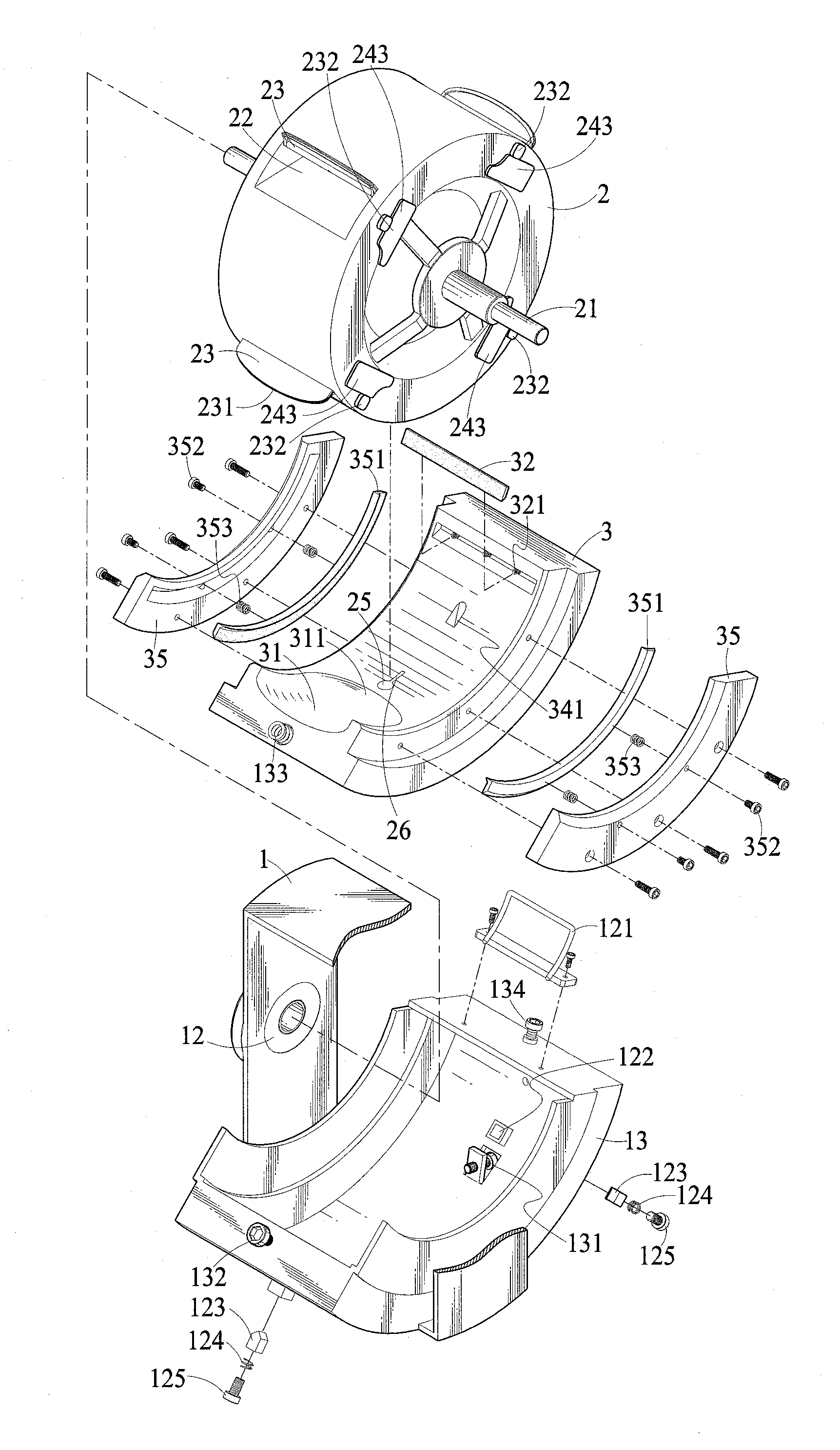
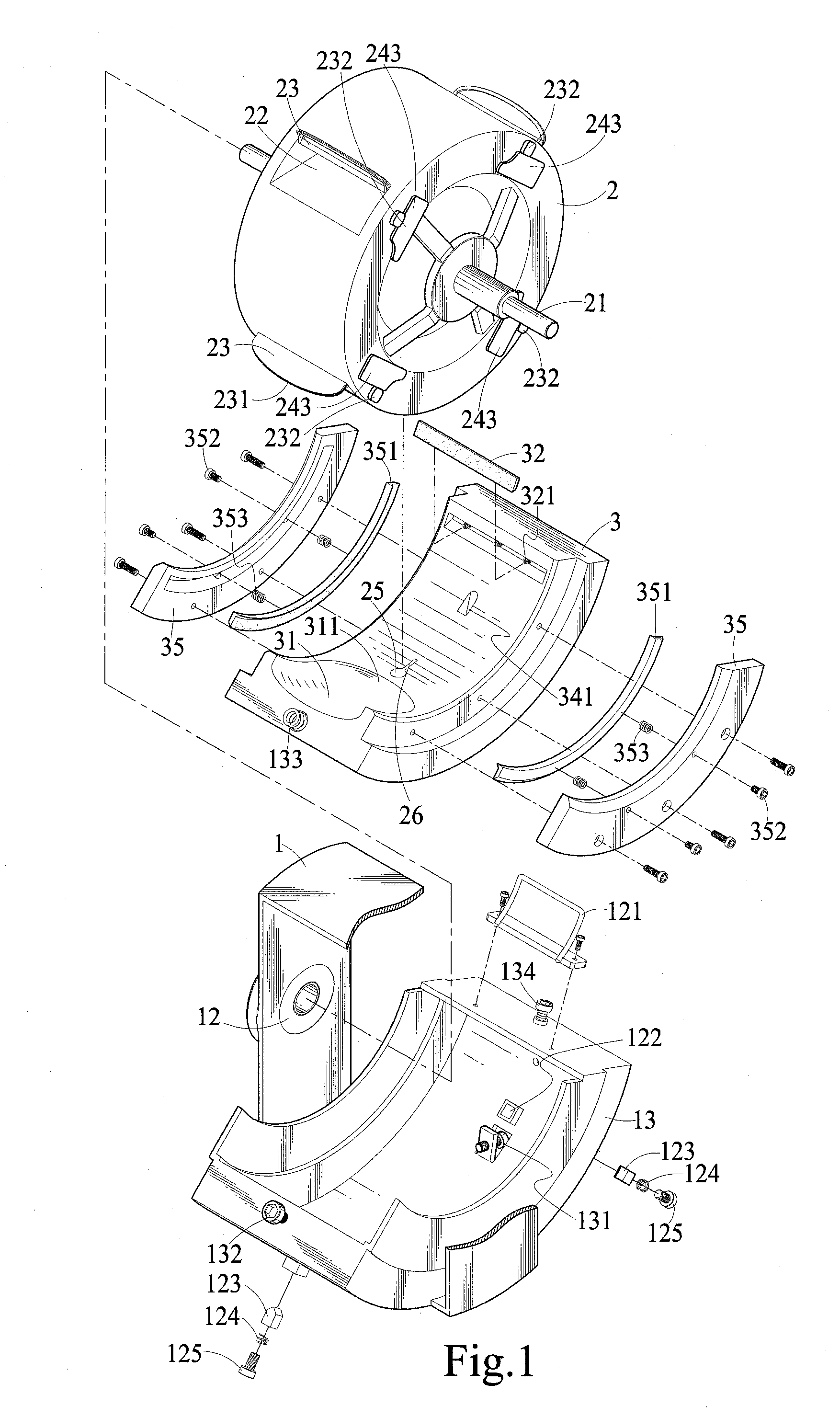
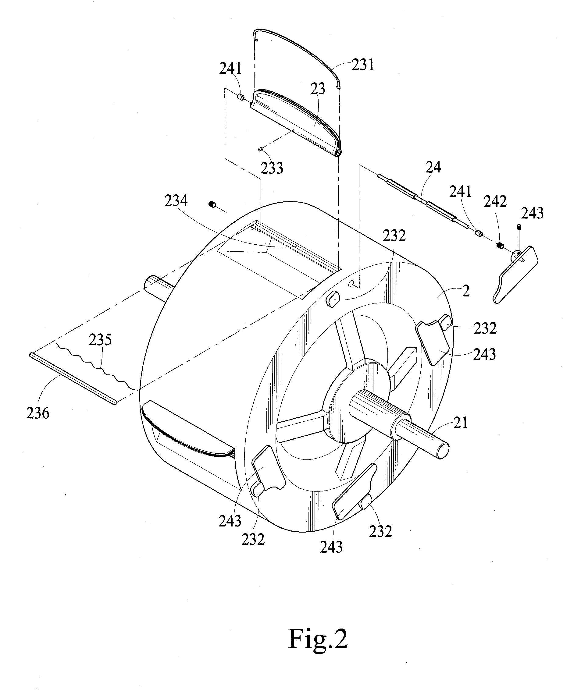
[0029]The structural assembly, overall operation and technical characteristics of the present invention will become apparent with the detailed description of a preferred embodiment and the illustration of the related drawings as follows.

[0030]With reference to FIGS. 1 to 6, the structure of the engine of the present invention eliminates the compression stroke among the four strokes, so that the fuel, the mixed gas, and high-pressure air are supplied from the outside, or an air compressor with appropriate power is used for this engine. Firstly, it is necessary to start a motor to rotate a turbine 2 (not shown in the figure), and then a main shaft 21 directly transmits a compressor, and an evaporator or a carburetor mixes and a fuel with a low ignition point such as liquefied petroleum gas and petroleum with air, and a gas inlet of the compressor sucks in the fuel for performing a compression to produce an output with a rising temperature introduced into a gas inlet 34 of the engine, ...


PUM


Abstract

A rotary engine includes one or more combustion chambers around a turbine, and a movable plate at an opening of the combustion chamber and rotated 90 degrees and protruded from the turbine. Both sides of the movable plate and the diameter of the turbine form an align straight line. The turbine comprises a slide member, a U-shape groove, a ditch with an open end coupled to the movable plate to form the explosion chamber. During explosion, the movable plate drives the turbine to rotate while eliminating the waste gases. The air current and pressure of the explosion apply forces to rotate the bottom of the combustion chamber. The volume of the explosion chamber can be extended to provide a relatively large open space since the movable plate can be moved and a higher pressure gases will be reduced rapidly so that the high-pressure gases can produce a greater force.

Description

CROSS-REFERENCE TO RELATED APPLICATIONS[0001]This application is a continuation-in part of U.S. patent application Ser. No. 12 / 382,585 filed on Mar. 19, 2009, which is a continuation-in-part of U.S. patent application Ser. No. 11 / 649,308 filed on 4 Jan. 2007, which is a continuation-in-part of U.S. application Ser. No. 11 / 114,059 filed on 26 Apr. 2005, which is a CIP of U.S. application Ser. No. 10 / 900,192 filed on 28 Jul. 2004 being a continuation-in-part of U.S. application Ser. No. 10 / 392,859 filed on 21 Mar. 2003, which had claimed priority on Taiwanese application filed on 3 Apr. 2002.BACKGROUND OF THE INVENTION[0002]1. Field of the Invention[0003]The present invention relates to a prime mover technology applied to automobiles, airplanes, ships, generators or motors, and more particularly to a rotary engine that adopts a turbine and a slide member installed concentrically with each other and processes a gas through four synchronous processes, respectively: intake, combustion, e...

Claims


Application Information

Patent Timeline
IPC IPC(8): F02B53/00
CPCF01D1/34F02B53/00Y02T50/671F02C5/04F02C5/02Y02T50/60
Inventor CHOU, JUNG-KUANG
Owner CHOU JUNG KUANG
Why Eureka
Try Eureka