Wind turbine with boundary layer control

a technology of boundary layer control and wind turbine, which is applied in the direction of wind turbines, motors, electrical equipment, etc., can solve the problems of large rotor diameters that require a high stiffness of blades, the ratio of extractable mechanical work to the power contained in the wind is limited to a value of 0.593, and the theoretical maximum cannot be reached

Inactive Publication Date: 2010-10-21
ACTIFLOW
View PDF5 Cites 42 Cited by
  • Summary
  • Abstract
  • Description
  • Claims
  • Application Information

AI Technical Summary

Benefits of technology

[0011]The boundary layer control system for the wind turbine blades provides the ability to locally apply on the blade surface active suction or blowing of air, depending on momentaneous loads acting on the blade. By applying suction, the aerodynamic loads on the blade are locally increased and the lift to drag ratio is increased, by applying blowing normal to the blade surface, the aerodynamic loads are locally decreased.
[0028]Boundary layer suction can be used to assist the start up of a wind turbine. During start up, the velocity of the air flowing over a blade of the wind turbine is relatively low. If the blade is not pitched in such a way that the angle of attack of the blade is small enough, then the airflow will separate from the blade surface and will not generate any lift to assist the start up of the wind turbine. Appling boundary layer suction to the blade, the flow will not separate from the blade surface and consequently the blade will generate a lift force enabling a more efficient start up of the wind turbine.

Problems solved by technology

However, large rotor diameters require a high stiffness of the blades and require an active control method for the aerodynamic loads acting on the wind turbine blades.
Even with an ideal airflow and lossless conversion, the ratio of extractable mechanical work to the power contained in the wind is limited to a value of 0.593.
In practice, this theoretical maximum can not be reached because of different aerodynamic losses.
Most of the aerodynamic losses are a result of the creation of a boundary layer on the wind turbine blade surface.
Wind turbines are subjected to significant unsteady loads resulting from wind shear, gusts, yaw misalignment and upwind turbine wakes, which significantly reduce the efficiency and the fatigue life of a wind turbine.
Rotor stall has been identified as one of the key causes of inefficiency and fatigue damage.
Moreover, the design of increasingly larger wind turbines is limited as rotor power and mass output are proportional to the second and third power of the wind turbine diameter respectively.
By closing the valves when the rotor is in an overspeed condition and thereby decreasing the air flow through the pathway and the outlet, the air stream along the blade surface is deteriorated whereby the aerodynamic lift decreases and the rotor is decelerated.

Method used


Image

  • Wind turbine with boundary layer control
  • Wind turbine with boundary layer control
  • Wind turbine with boundary layer control

Examples


Embodiment Construction

[0047]The invention has for an object to provide an improved boundary layer control system for wind turbine blades which can be used for multiple purposes, depending on the momentaneous weather conditions and loads acting on wind turbine blades.

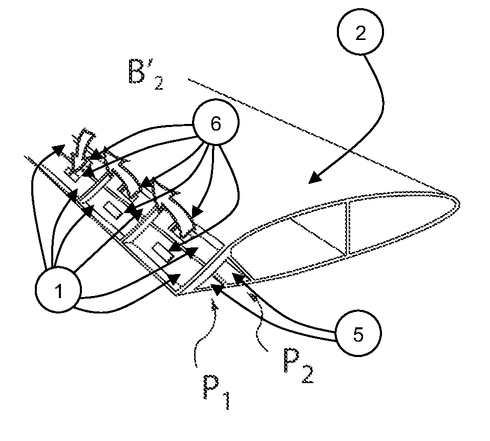
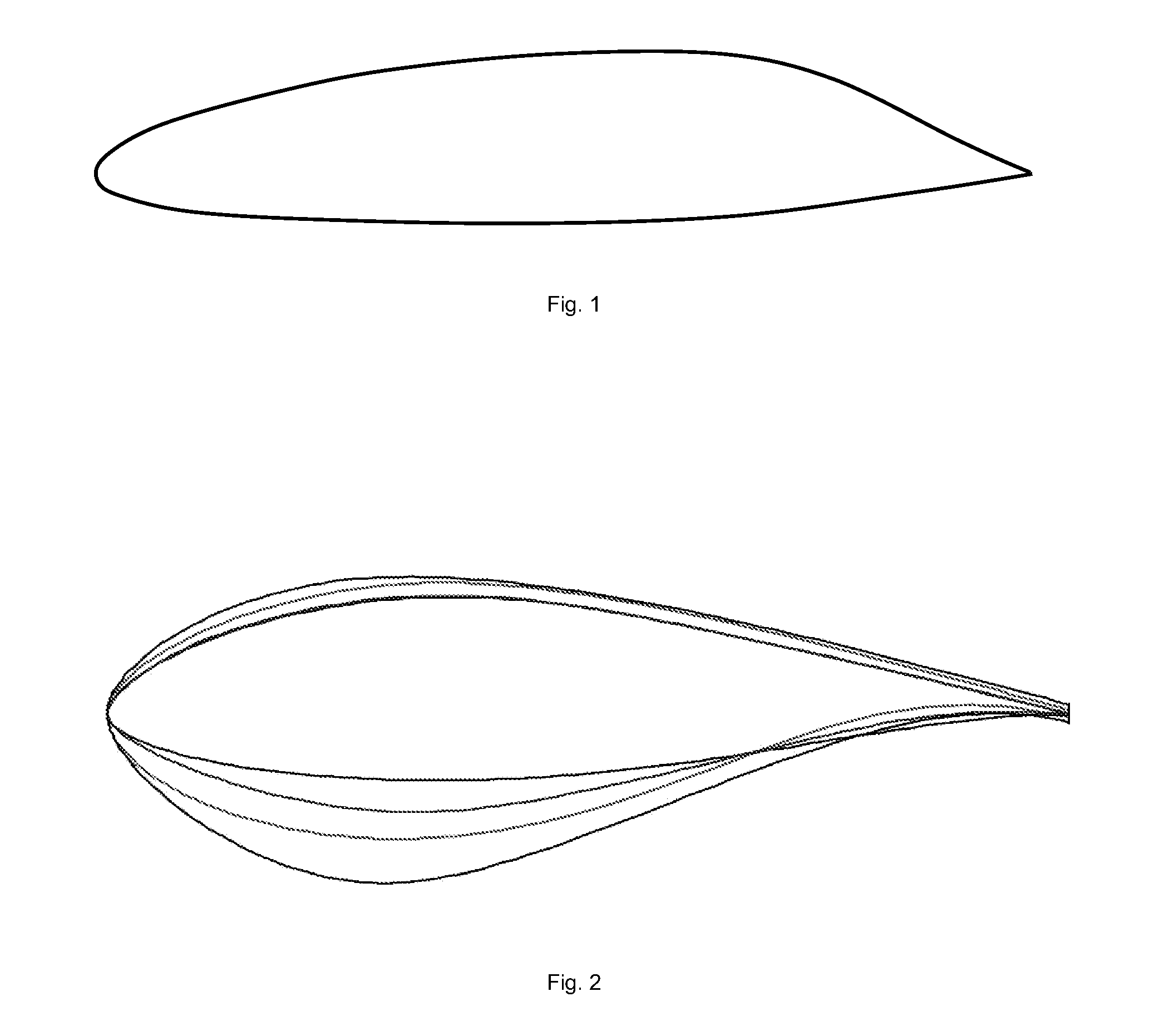
[0048]The boundary layer control system can be installed in a wind turbine blade design using conventional blade profiles, but it can also be integrated in a new blade design using blade profiles which are optimized for the use of the boundary layer control system (FIGS. 1 and 2).

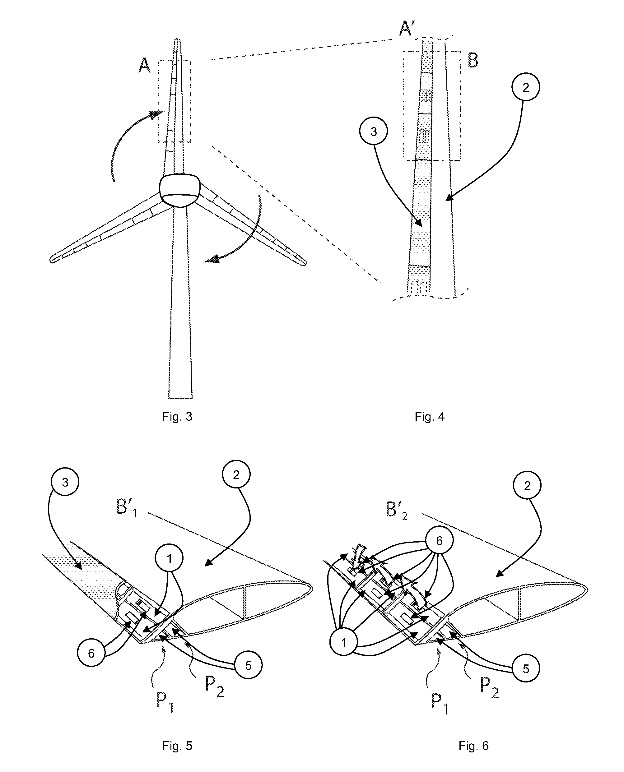
[0049]The boundary layer control system comprises a plurality of pressure chambers, indicated by reference numeral 1 in FIGS. 5, 6, 7 and 8, situated below the surface of the extrados (the rear side or suction side) of blade 2 (see FIGS. 4, 5, 6, 7, 8, 9, 12, 13 and 15), the surface material being partially replaced by a porous material 3 (shown in FIGS. 4, 5, 7, 8, 9, 12, 13 and 15). The pressure chamber 1 is a cavity in the wind turbine blade just underneath the bl...


PUM


Abstract

The invention relates to a wind turbine comprising a rotor with a hub and turbine blades, and further comprising a boundary layer control system for the turbine blades. A plurality of pressure chambers is located in the blade distributed over the length of the blade. Each pressure chamber is in communication with the outside of the blade through one or more corresponding openings in the outer surface of the turbine blade. Furthermore a suction channel and a blow channel extend inside the blade for supplying an underpressure and an overpressure respectively to the pressure chamber, each pressure chamber being connected to at least one of said channels through an air passage in which an actively operable valve is located. The valve is connected to a control unit for selectively bringing the pressure chamber into communication with or close it off from said channel(s) so as to blow air out of the pressure chamber or suck air into the pressure chamber through the corresponding opening(s) in the blade surface.

Description

CROSS-REFERENCE TO RELATED APPLICATIONS[0001]This application is the National Stage of International Application No. PCT / NL2008 / 000235, filed Oct. 21, 2008, which claims the benefit of EP Application No. 07075909.7, filed Oct. 22, 2007, the contents of which is incorporated by reference herein.FIELD OF THE INVENTION[0002]The present invention relates to a wind turbine comprising a rotor with turbine blades, and further comprising a boundary layer control system for the turbine blades.BACKGROUND OF THE INVENTION[0003]The wind turbine industry is growing very rapidly. Due to the increasing prices of fossil fuels and due to environmental concerns, there is a growing demand for green energy. To ensure the lasting success of wind turbines and to meet the future requirements of wind turbines, lots of R&D is being carried out on all aspects of a wind turbine.[0004]Considering modern horizontal-axis wind turbines, the goal of the R&D is maximizing the energy production of a wind turbine, di...

Claims


Application Information

Patent Timeline
Patent Type & Authority Applications(United States)
IPC IPC(8): F03B11/00F03D9/00
CPCF03D1/0608F03D11/022Y02E10/722Y02E10/721F05B2240/301F03D15/05F03D7/022Y02E10/72
Inventor CAMPE, ROYTERRY, ERIC LOUIS NORBERT
Owner ACTIFLOW
Why Eureka
Try Eureka